

Pratite promene cene putem maila
- Da bi dobijali obaveštenja o promeni cene potrebno je da kliknete Prati oglas dugme koje se nalazi na dnu svakog oglasa i unesete Vašu mail adresu.
1-16 od 16 rezultata
Broj oglasa
Prikaz
1-16 od 16
1-16 od 16 rezultata
Prikaz
Prati pretragu "exit"
Vi se opustite, Gogi će Vas obavestiti kad pronađe nove oglase za tražene ključne reči.
Gogi će vas obavestiti kada pronađe nove oglase.
Režim promene aktivan!
Upravo ste u režimu promene sačuvane pretrage za frazu .
Možete da promenite frazu ili filtere i sačuvate trenutno stanje
-
Mašine i alati chevron_right Ručni alat i rezervni delovi
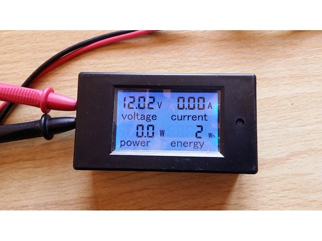
P14 A.Function 1. Electrical parameter measurement function (voltage, current, active power, energy) 2. Voltage alarm function (over voltage alarm threshold, backlight and voltage flashing to alarm). 3. The reset function of energy key. 4. Store data when power off. 5. Large-screen LCD (display voltage, current, active power, energy at the same time) 6. Backlight function. B.Appearance and Key function I. Display Interface Display interface is large-screen LCD, it can display voltage, current, power, energy parameters at the same time. II.Display format 1.Power: test range: 0~5kW within 1KW, the display format is 0.0~999.9W; 1KW and above, the display format is 1000~4999W. 2.Energy: test range: 0~9999kWh Within 10KWh, the display format is 0~9999Wh; 10kWh and above, the display format is 10~9999kWh. 3.Voltage: test range: 6.5~100V Display format: 6.50~99.99V 4.Current: test range: 0~50A Display format: 0.00~49.99 III. Key 1.Backlight control Short press the key to turn on or off the backlight, the backlight has memory function, it can store the on or off state when power off. 2.Reset energy Step1: Long press the key until the power display area display “CLr”, then release the key. Step2: At this moment, the energy is flashing to prompt this is the energy reset state, if short press the key again, then the energy value is cleared and exit the reset flashing state. Step 3: If there is no operation within 5 seconds, it means the energy value is not cleared and will exit the reset state. 3.Set voltage alarm threshold Step1: Long press the key until the power display area display “SET”, then release the key. Step2: After enter this state, the voltage area display the current high voltage alarm value, the current area display the current low voltage alarm value and the last digit begin to flash, then you can short press to plus 1, when there is no operation over 3 seconds, it will switch the digit position automatically, from the high voltage alarm value to the low voltage alarm value, there are total six digits, the range of the voltage alarm threshold is 6.5-99.9V; Step3: After finish the setting, long press the key until the screen display “PASS”,that means you set successfully and will exit the setting state automatically. 4.Choose measuring range Step1: Long press the key until the power area display “Curr”, then release the key Step2: At this moment, the current area display “100A”, short press the key to switch between“100A”and “50A”, to prompt the range of the external shunt is 100A/75mV or 50A/75mV, please note that this meter can only use these two specification shunt. Step3: Long press the key to exit the setting state or after no operation within 3 seconds it will store automatically and exit the setting state. C. Precautions 1. This module is suitable for indoor, please do not use outdoor. 2. Applied load should not exceed the rated voltage, current. 3. Wiring order can’t be wrong. D. Specification parameters 1. Working voltage: 6.5-100VDC 2. Test voltage: 6.5-100VDC 3. Rated power: 50A/5000W 4. Measurement accuracy: 1.0 grade Package include 100% Brand New 1 x 4in1 50-100A DC digital multi-function meter + 50A 75mv shunt.
-
Mašine i alati chevron_right Ručni alat i rezervni delovi
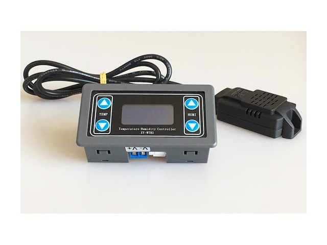
P16 XY-WTH1Temperature and humidity control module high precision digital display word double output automatic constant temperature and humidity control panel Product adopts industrial-grade chip, high-precision SHT20 temperature and humidity sensor. Product Function: Product features are two main types of classification: the functions of temperature and humidity; Function of temperature are as follows: The automatic identification of work mode: The system automatically according to the start/stop temperature, identify work mode; Start temperature > stop temperature, cooling mode`C`. Start temperature < stop temperature, heating mode `H`. Cooling mode: When the temperature≥Start temperature,relay conduction,red led on, refrigeration equipment begin to work; When the temperature≤Stop temperature,relay disconnect, red led off, refrigeration equipment stop to work; Heating mode: When the temperature≤Start temperature,relay conduction, red led on, heating equipment begin to work; When the temperature≥Stop temperature,relay disconnect, red led off, heating equipment stop to work; Temperature correction function OFE (-10.0 ~ 10℃): The system is working for a long time and may be biased, through this function correction, the actual temperature = measuring temperature + calibration value; How to set the start/stop temperature: 1. In the running interface, Long Press ` TM+ ` key more than 3 seconds, into the start temperature settings interface, can be modified by TM+ TM-key, to be modified, waiting for 6s automatic exit and save; 2. In the running interface, Long Press ` TM-` key more than 3 seconds, into the stop temperature settings interface,can be modified by TM+ TM-key, to be modified after the parameters, waiting for 6s automatic exit and save; The humidity function is as follows: The automatic identification of work mode: The system automatically according to the start/stop humidity, identify work mode; Start humidity> stop humidity, dehumidificationmode`D`. Start humidity< stop humidity, humidificationmode `E`. Dehumidificationmode: When the humidity≥Start humidity,relay conduction, green led on, dehumidification equipment begin to work; When the humidity≤Stophumidity,relay disconnect, green led off, dehumidificationequipment stop to work; Humidificationmode: When the humidity≤Start humidity,relay conduction, green led on, humidificationequipment begin to work; When the humidity≥Stophumidity,relay disconnect, green led off, humidificationequipment stop to work; Humidificationcorrection function RH (-10.0 ~ 10%): The system is working for a long time and may be biased, through this function correction, the actual humidity= measuring humidity+ calibration value; How to set the start/stop humidity: 1. In the running interface, Long Press ` RH+ ` key more than 3 seconds, into the start humiditysettings interface, can be modified by RH+ RH- key, to be modified, waiting for 6s automatic exit and save; 2. In the running interface, Long Press ` RH-` key more than 3 seconds, into the stop humiditysettings interface, can be modified by RH+ RH- key, to be modified after the parameters, waiting for 6s automatic exit and save; Running Interface Description: Working mode shows that the current mode (`H/C`, `E/d`) will be synchronized at the front of temperature/humidity, when the setting of temperature/humidity and stop temperature/humidity are completed. Any relay conduction, the upper-left corner of the interface display `out`, if the temperature relay conduction, the flashing display temperature working mode `H/C` to show reminders; if the humidity relay conduction, then flashing display humidity working mode `E/d`, as a reminder; Other features: Parameter remote read/set: Through the UART, set the starting temperature/humidity, stop temperature/humidity, temperature/humidity correction parameters; temperature/Humidity Real-time reporting: If the temperature/humidity reporting function is turned on, the product will detect the temperature/humidity and relay status by the 1s interval, and pass the UART to the terminal to facilitate data collection; Relay enabling (by default): If the relay is disable, the relay remains disconnected; How to modify the temperature/humidity correction value: 1. In the operating interface, double-click the ` TM+ ` key to enter the correction of the set interface, the downward display correction of the type, the upward display of specific values; (OFE: Temperature correction value RH: Humidity correction value) At this time by a short press ` TM-` key, switch to modify the parameters, through the RH+ RH-key, modify the specific value of the support long press short; 3. When the parameters have been modified, double-click the ` TM+ ` key, exit the correction positive setting interface, and save the data; How to enable/disable relay: In the running interface, Short press ` TM-` key,enable/disablethe temperature relay(ON: enableOFF:disable), back to the running interface, if the temperature relay is disable, the temperature symbol ` ℃ ` flashes to remind. In the running interface, Short press ` RH-` key, enable/disable the humidity relay (ON: enable OFF: disable), back to the running interface, if the humidity relay is disable, the humidity symbol `% ` flashes, as a reminder. Serial control(TTL level) BaudRate:9600bps Data bits :8 stop bits :1 crc :none Flow control :none
-
Mašine i alati chevron_right Ručni alat i rezervni delovi
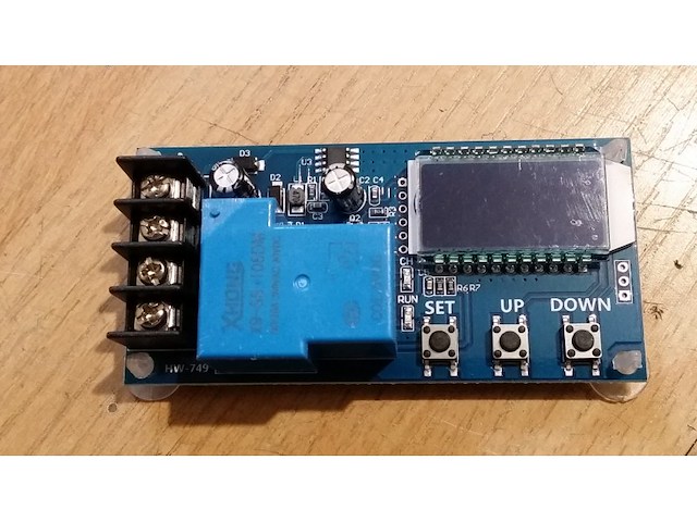
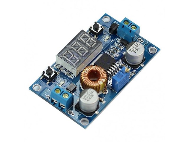
P01 1. Support Lead-acid battery and Acting Battery,voltage range:6V~60V; 2. Can display voltage,percent of battery,charging time at the same time through LCD; 3. The function is very powerful,realizes the automatic charge control, the control charge time, also may set up and uploads the corresponding parameter through the serial port; Function description 1. Automatic Charge control function: By setting the volt-HI:`UP` volt-LI:`dn`;When the battery voltage is below the volt-LI:`dn`,the relay leads,the charger begins to charge the battery;when the battery voltage is up to volt-HI:`UP`,the relay is diconnected and the automatic charge is completed once; 2. Charge Time Control Function: How to turn on the time control function? After entering the parameter set, set the parameter op is non-zero, then turn on the time control function, op default parameter is:--:--h, the default does not turn on time control function; After the opening Time control function (OP is non-zero), when the battery voltage is the lower volt-LI`dn`, the charger began to charge the battery, the system began to clock; During the timing, the battery voltage ≥ volt-HI`UP`, relay disconnect; If the OP time is up, the battery voltage is still the lower volt-LI`dn`, the relay keeps the conduction, automatically closes the charge time control function, and flashes the H:ER to remind the user, the time parameter setting is unreasonable; Press any key to stop flashing; Note: Time format: 00:59 (00 for hours, 59 for minutes) The maximum time is 99:59, which is 100 hours. 3. Serial data upload and parameter setting function: The system supports UART data upload and parameter setting UART:115200,8,1 Cmd Func on Relays enable to open off Relays disable to open start Start data upload stop Stop data upload read Read the param setting dw10.0 Set volt-LI:`dn` up20.0 Set volt-HI:`UP` xx:xx Set the charge time OP 00:00 stop charge time Data Upload message Format: Battery voltage + battery percent + charge time + charge status 12.0V,020%,00:10,OP Parameter Setting a) Press and hold the SET key to enter the setting interface; b) Switch the parameters you want to set by short press SET; c) After the selection of parameters, can be set by the UP/DOWN key to support the short press, long press (fast increase or decrease); To set other parameters, repeat step b, c); d) After all parameters are set, long press set key to exit and save; The Key Function Description: In the Run interface (main interface): Short press SET button to display the current set of parameters; Short press UP button, toggle display charge percentage and charging time; Short Press DOWN button, select Turn on/off relay enabling, if the relay can be closed, will show ` off ` as a reminder; Long press UP button, switch low power state on:No operation in 10 minutes turn off backlight OFF: Backlight is always bright Long press SET button,enter the parameter settings. Calculation of voltage percentage: voltage percentage = battery voltage/(volt-HI – volt-LI) Additional Features a) Charging time recording function: not open charging time control, the product will record a full time, when the entry time display interface, flashing display charging time, and then exit time display interface or next charge to open (relay conduction) when empty; b) Automatic parameter detection: When the parameters are set, exit, if volt-LI dn≥ volt-HI UP, the system will flash display `ERR` as a reminder; c) Battery Access detection: This product attached to the battery, if not connected to the battery, the system will be shown in the downlink `NbE` as a reminder Analysis of common failures Q: How much is suitable for V level use? How much v voltage does this module fit? A: This section is suitable for the minimum 6V, the highest 60V voltage range, the maximum expenditure level 48V, because 48V battery full of electricity in 60V, and then a high fever, if your battery is higher than 48V, please select other section. Q: The power of the subsequent electrical appliances snapped! LED flashing? A: This is because your charging current is too large or the battery capacity is too small to cause a power to immediately reach the voltage limit, relay disconnect, disconnect, the voltage and quickly down to the lower voltage, and began to recharge, cycle, at this time you want to reduce the charging current only line, Usually the charging current is the battery capacity of the very 1 to 1.5, such as 20AH battery charging current generally around 2-3a! Note that a large current charge will cause the battery fever accelerated aging, drum kits and even explosions! Q: What control mode? Can I cycle the charge automatically? Can I use the side charge? Can I limit the flow? A: This is voltage control, For example, set the voltage limit of 12.0V, voltage up to 14.5V, voltage charge to 14.5V this value on the power off, voltage down to the 12.0V relay closed and start charging, can be filled with side, voltage control mode only to turn off and open, can not limit the flow, charging current completely depends on your charger! Q: Input 12V can or not charge 24V battery, or enter 48V can give 12V battery charge? A:This is a simple voltage controller, only play the role of switch, can not swing to the battery charge, so you want to give what battery charge to be ready what kind of charger! It`s necessary!
-
Mašine i alati chevron_right Ručni alat i rezervni delovi
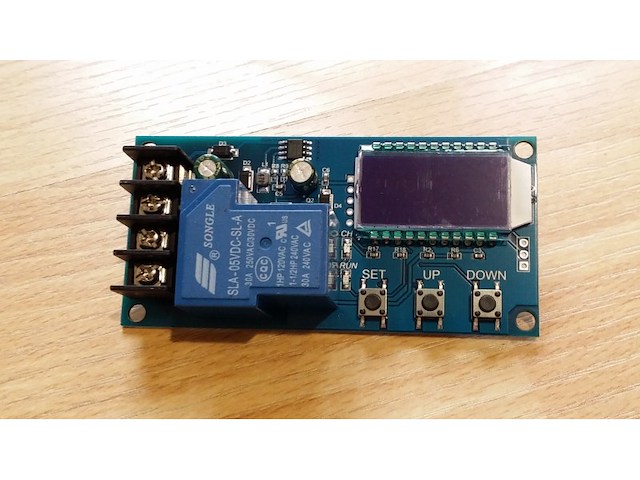
P12 1. Support Lead-acid battery and Acting Battery,voltage range:6V~60V; 2. Can display voltage,percent of battery,charging time at the same time through LCD; 3. The function is very powerful,realizes the automatic charge control, the control charge time, also may set up and uploads the corresponding parameter through the serial port; Function description 1. Automatic Charge control function: By setting the volt-HI:`UP` volt-LI:`dn`;When the battery voltage is below the volt-LI:`dn`,the relay leads,the charger begins to charge the battery;when the battery voltage is up to volt-HI:`UP`,the relay is diconnected and the automatic charge is completed once; 2. Charge Time Control Function: How to turn on the time control function? After entering the parameter set, set the parameter op is non-zero, then turn on the time control function, op default parameter is:--:--h, the default does not turn on time control function; After the opening Time control function (OP is non-zero), when the battery voltage is the lower volt-LI`dn`, the charger began to charge the battery, the system began to clock; During the timing, the battery voltage ≥ volt-HI`UP`, relay disconnect; If the OP time is up, the battery voltage is still the lower volt-LI`dn`, the relay keeps the conduction, automatically closes the charge time control function, and flashes the H:ER to remind the user, the time parameter setting is unreasonable; Press any key to stop flashing; Note: Time format: 00:59 (00 for hours, 59 for minutes) The maximum time is 99:59, which is 100 hours. 3. Serial data upload and parameter setting function: The system supports UART data upload and parameter setting UART:115200,8,1 Cmd Func on Relays enable to open off Relays disable to open start Start data upload stop Stop data upload read Read the param setting dw10.0 Set volt-LI:`dn` up20.0 Set volt-HI:`UP` xx:xx Set the charge time OP 00:00 stop charge time Data Upload message Format: Battery voltage + battery percent + charge time + charge status 12.0V,020%,00:10,OP Parameter Setting a) Press and hold the SET key to enter the setting interface; b) Switch the parameters you want to set by short press SET; c) After the selection of parameters, can be set by the UP/DOWN key to support the short press, long press (fast increase or decrease); To set other parameters, repeat step b, c); d) After all parameters are set, long press set key to exit and save; The Key Function Description: In the Run interface (main interface): Short press SET button to display the current set of parameters; Short press UP button, toggle display charge percentage and charging time; Short Press DOWN button, select Turn on/off relay enabling, if the relay can be closed, will show ` off ` as a reminder; Long press UP button, switch low power state on:No operation in 10 minutes turn off backlight OFF: Backlight is always bright Long press SET button,enter the parameter settings. Calculation of voltage percentage: voltage percentage = battery voltage/(volt-HI – volt-LI) Additional Features a) Charging time recording function: not open charging time control, the product will record a full time, when the entry time display interface, flashing display charging time, and then exit time display interface or next charge to open (relay conduction) when empty; b) Automatic parameter detection: When the parameters are set, exit, if volt-LI dn≥ volt-HI UP, the system will flash display `ERR` as a reminder; c) Battery Access detection: This product attached to the battery, if not connected to the battery, the system will be shown in the downlink `NbE` as a reminder Analysis of common failures Q: How much is suitable for V level use? How much v voltage does this module fit? A: This section is suitable for the minimum 6V, the highest 60V voltage range, the maximum expenditure level 48V, because 48V battery full of electricity in 60V, and then a high fever, if your battery is higher than 48V, please select other section. Q: The power of the subsequent electrical appliances snapped! LED flashing? A: This is because your charging current is too large or the battery capacity is too small to cause a power to immediately reach the voltage limit, relay disconnect, disconnect, the voltage and quickly down to the lower voltage, and began to recharge, cycle, at this time you want to reduce the charging current only line, Usually the charging current is the battery capacity of the very 1 to 1.5, such as 20AH battery charging current generally around 2-3a! Note that a large current charge will cause the battery fever accelerated aging, drum kits and even explosions! Q: What control mode? Can I cycle the charge automatically? Can I use the side charge? Can I limit the flow? A: This is voltage control, For example, set the voltage limit of 12.0V, voltage up to 14.5V, voltage charge to 14.5V this value on the power off, voltage down to the 12.0V relay closed and start charging, can be filled with side, voltage control mode only to turn off and open, can not limit the flow, charging current completely depends on your charger! Q: Input 12V can or not charge 24V battery, or enter 48V can give 12V battery charge? A:This is a simple voltage controller, only play the role of switch, can not swing to the battery charge, so you want to give what battery charge to be ready what kind of charger! It`s necessary!
-
Mašine i alati chevron_right Ručni alat i rezervni delovi
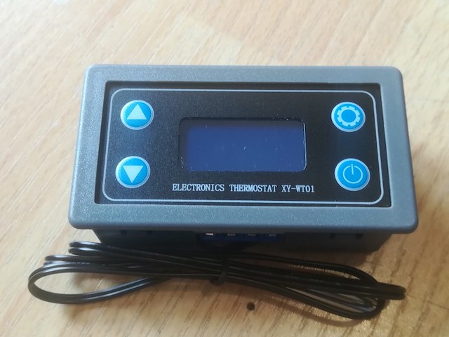
P16 Xy-t01 digital temperature controller high precision digital display temperature controller module refrigeration and heating Product functions: 1. Heating mode `H`: When the detection temperature ≤ the set temperature - return difference temperature, the relay is turned on and the heating equipment starts to work; When the detection temperature is ≥ the set temperature, the relay is disconnected and the heating equipment stops working; 2. Refrigeration mode `C`: When the detection temperature is ≥ the set temperature + return difference temperature, the relay is turned on and the refrigeration equipment starts to work; When the detection temperature is less than or equal to the set temperature, the relay is disconnected and the refrigeration equipment stops working; 3. High temperature alarm function ala: When the actual temperature is greater than or equal to the alarm temperature, the system will start the audible and visual alarm, disconnect the relay, and press any key to stop the audible and visual alarm; 4. Delayed start of OPH: After completing a normal heating or cooling work, the system starts to count T. only when t ≥ OPH, the system can carry out the next round of heating or cooling work; 5. Temperature correction function ofe (- 10.0 ~ 10.0 ℃): If the system works for a long time, there may be deviation. Through this function, the actual temperature = measured temperature + calibrated value; 6. Remote reading / setting of parameters: Start temperature, stop temperature, temperature correction and other parameters can be set through UART; 7. Real time temperature reporting: If the temperature reporting function is enabled, the product will transmit the detected temperature to the terminal through UART at an interval of 1s for data acquisition; 8. Relay enable (default on): If the relay is turned off and enabled, the relay remains disconnected; 9. Restore factory settings: Press stop and set for more than 3S at the same time to restore the factory setting; Operating mode / setting temperature / return difference temperature setting: 1. In the operation interface, briefly press the set key to enter the quick setting interface; 2. Press the temperature setting / difference key to enter the working mode setting interface (short time setting); 3. Use the up down key to modify the parameter value, and support short press / long press; 4. Press and hold set for more than 3S or for 6S without any key operation, exit the quick setting interface and save the parameters; Alarm temperature / delay start setting / temperature correction: 1. In the operation interface, long press set for more than 3S to enter the parameter setting interface; 2. After entering the parameter setting interface, briefly press the set key to switch the parameters to be set (alarm temperature / delayed start setting / temperature correction); 3. Use the up down key to modify the parameter value, and support short press / long press; 4. Press and hold set for more than 3S or for 6S without any key operation, exit the parameter setting interface and save the parameters; How to turn on high temperature alarm (off by default): Enter the parameter setting interface, switch to the alarm parameter ala interface, and turn on or off the high temperature alarm function by short pressing the stop key; If the high temperature alarm function is off, ALA displays` ---- `as a reminder; How to turn on delayed start (off by default): Enter the parameter setting interface, switch to the alarm parameter OPH interface, and turn on or off the high temperature alarm function by short pressing the stop key; If the high temperature alarm function is off, OPH displays` ---- `as a reminder; Serial port control (single chip microcomputer TTL level communication) Communication standard: 9600bps data bit: 8 Stop bit: 1 Check bit: None Flow control: None
-
Mašine i alati chevron_right Ručni alat i rezervni delovi
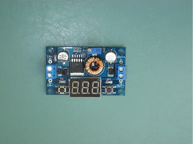
P06 Performance parameters: 1.Input voltage range:4-38VDC(Note:input voltage not exceeding 38V) 2.Output voltage range:1.25-36VDC adjustable 3.Output current:5A max 4.Output power: 75W 5.voltmeter range: 4 to 40V, error ±0.1V 6.Operating frequency: 180KHz 7.High efficiency up to 96% 8.Built in thermal shutdown function 9.Built in current limit function 10.Built in output short protection function 11.Input reverse polarity protection: None (if required, high current diode in series with the input). 12.L x W x H =6*3.7*1.8CM Features: 1. LED power indicator. 2. Button to switch measurement of the input or output voltage, and LED indicates the current measurement of the input or output voltage; The nixie tube can be turned off by another button. Mentioned states are able to be memorized, is not lost even if the power is disconnected. (On-board marked `IN` LED is turned on, the nixie tube display input voltage value, `OUT` LED bright display is the output voltage value). 3. Special launch, the voltmeter calibration function, will never exist voltmeter inaccurate! Voltmeter calibration method: (1) Output voltage calibration steps Step 1, adjust the right button so that `OUT` LED lighted, the voltmeter shows the value of output voltage; Press the right button for more than 2 seconds, release, voltmeter and `OUT` LED flashes in synchronization so that you enter the output voltage calibration mode. Step 2, press the right button (normal speed), the voltage value is adding up a unit; Press the left button, minus a unit; Due to a unit is less than 0.1V, the minimum voltage display to 0.1V, so you need to continuously press 1-5 times to see the voltmeter change 0.1V, how many times voltmeter change 0.1V by pressing the key, depending on the current display voltage, the higher the voltage, the fewer the number of press. Step 3, press the right button for more than 2 seconds, release, to exit the output voltage calibration mode. All parameters set to automatically power down to save. (2) Input voltage calibration steps Step 1, adjust the right button so that `IN` LED lighted, the voltmeter shows the value of input voltage; press the right button for more than 2 seconds, release, voltmeter and `IN` LED flashes in synchronization so that you enter the input voltage calibration mode. Steps 2 and 3, consistent with the output voltage calibration method.
-
Mašine i alati chevron_right Ručni alat i rezervni delovi
P06 Specification: This product is a 180 KHz fixed frequency PWM buck (step-down) DC/DC module,capable of driving a 5A load with high efficiency, low ripple and excellent line and load regulation.The module with a voltage meter to display the input voltage and output voltage, and the voltage can be corrected through the button to improve the accuracy of the voltmeter. Features: 1. LED power indicator. 2. Button to switch measurement of the input or output voltage, and LED indicates the current measurement of the input or output voltage; The nixie tube can be turned off by another button. Mentioned states are able to be memorized, is not lost even if the power is disconnected. (On-board marked `IN` LED is turned on, the nixie tube display input voltage value, `OUT` LED bright display is the output voltage value). 3. Special launch, the voltmeter calibration function, will never exist voltmeter inaccurate! Voltmeter calibration method: (1) Output voltage calibration steps Step 1, adjust the right button so that `OUT` LED lighted, the voltmeter shows the value of output voltage; Press the right button for more than 2 seconds, release, voltmeter and `OUT` LED flashes in synchronization so that you enter the output voltage calibration mode. Step 2, press the right button (normal speed), the voltage value is adding up a unit; Press the left button, minus a unit; Due to a unit is less than 0.1V, the minimum voltage display to 0.1V, so you need to continuously press 1-5 times to see the voltmeter change 0.1V, how many times voltmeter change 0.1V by pressing the key, depending on the current display voltage, the higher the voltage, the fewer the number of press. Step 3, press the right button for more than 2 seconds, release, to exit the output voltage calibration mode. All parameters set to automatically power down to save. (2) Input voltage calibration steps Step 1, adjust the right button so that `IN` LED lighted, the voltmeter shows the value of input voltage; press the right button for more than 2 seconds, release, voltmeter and `IN` LED flashes in synchronization so that you enter the input voltage calibration mode. Steps 2 and 3, consistent with the output voltage calibration method. Performance parameters: 1、Input voltage range:4~38VDC(Note:input voltage not exceeding 38V) 2、Output voltage range:1.25-36VDC adjustable 3、Output current: 0-5A 4、Output power: 75W 5、voltmeter range: 4 to 40V, error ±0.1V 6、Operating frequency: 180KHz 7、High efficiency up to 96% 8、Built in thermal shutdown function 9、Built in current limit function 10、Built in output short protection function 11、Input reverse polarity protection: None (if required, high current diode in series with the input). 12、L x W x H =6.6*3.9*1.8CM application: The DC/DC buck module applications the input voltage is higher than the output voltage of the buck field, such as battery, power transformer, DIY adjustable regulated power supply, LCD Monitor and LCD TV,portable instrument power supply,telecom/networking equipment,24V vehicle notebook power supply,industrial equipment buck.12V buck to 3.3V, 12V buck to 5V, 24V buck to 5V,24V buck to 12V, 36V buck to 24V etc.
-
Mašine i alati chevron_right Ručni alat i rezervni delovi
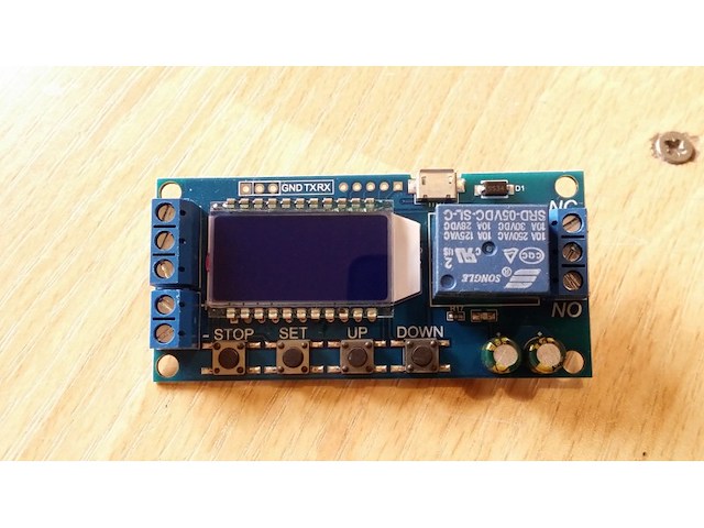
P04 Product Highlights: 1. Display with LCD two columns, Can display parameters directly; 2. Trigger mode: high and low level,switch quantity.meet most of the needs. 3. Power supply: 6~30V, also supports micro USB 5.0V, very convenient.Anti back connection of power supply. 4. Parameters can be modified via UART. 5. Stop button to provide emergency stop function. 6. 5 minutes without any operation into a low-power state. Any action wake up. 7. OP/CL/LOP params can be modified individually 8. All parameters are automatically saved by power off. Working Mode Introduction(P1~P7) P1: After the signal is triggered, the relay conduction in OP time then disconnects; In the OP time, the signal is invalid. P2: After the signal is triggered, the relay conduction in OP time then disconnects; In the OP time, the signal triggers a new timer. P3: After the signal is triggered, the relay conduction in OP time then disconnects; In the OP time, signal trigger reset timer,relay disconnected and stop timing. P4: When triggered, After the relay is disconnected from CL time, relay conduction OP time, after timing is complete, disconnect relay. P5: When triggered, After the relay conduction op time, the relay disconnects the CL time, and then loops the above action, gives the signal again in the loop, relays disconnect, stops the timer, and the number of cycles (LOP) can be set; P6: When triggered, After the relay conduction op time, the relay disconnects the CL time, and then loops the above action, signal is invalid in the loop, the number of cycles (LOP) can be set; P7: Signal hold function: The signal is maintained, the timing is cleared, and the relay conduction; when the signal disappears, the relay disconnects after the timing OP; during the timing, there is another signal and the timing is cleared; Product Parameters: 1. Power Supply: 6V~30V and micro USB 5.0 V 2. Trigger signal source: High level(3.0V~24.0V),Low level(0.0V ~0.2V),Switch signal. 3. Maxmum Output load: DC 30V 5A and AC 220V 5A. 4. Static Current: 15mA Operating current: 50mA. 5. Service life: more than 100,000 times; working temperature: -40-85°C; size: 8.0*3.8*1.9cm. 6. Optocoupler isolation,Strong anti-interference ability, Industrial grade circuit board Timing Range: 0.01 sec~9999 min How to choose the timing range: In the OP/CL parameter modification interface, press the STOP button shortly to select the timing range. XXXX Timing range:1sec~9999sec XXX.X Timing range:0.1sec~999.9sec XX.XX Timing range:0.01sec~99.99sec X.X.X.X Timing range:1min~999.9min For example, if you want to set the OP to 3.2 seconds, move the decimal point to ten digits. LCD display 003.2 Parameter Description: OP on-time, CL off time, LOP cycle times (1 - 9999 times, `----` represents an infinite number of cycles) Parameter Settings: a) Press and hold the SET key to enter the setting interface; b) First set the working mode, work mode flashes reminder, set the working mode by pressing the UP / DOWN keys; c) Short press the SET button to select the working mode and enter the system parameter settings. d) In the system parameter setting interface, press SET key to switch the system parameters to be modified, and press / long press UP/DOWN key to modify. (Note: Short press SET in P-1~P-3, P-7 mode is invalid); e) In the OP/CL parameter modification interface, short press STOP to switch the timer unit (1s/0.1s/0.01s/1min); f) After all parameters are set, press and hold the SET button for more than 2 seconds to release the hand, save the parameter settings and exit the setting interface
-
Mašine i alati chevron_right Ručni alat i rezervni delovi
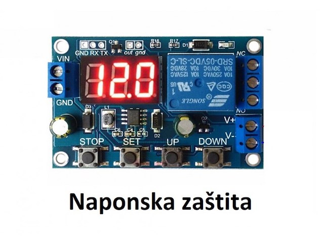
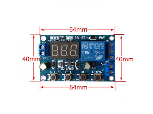
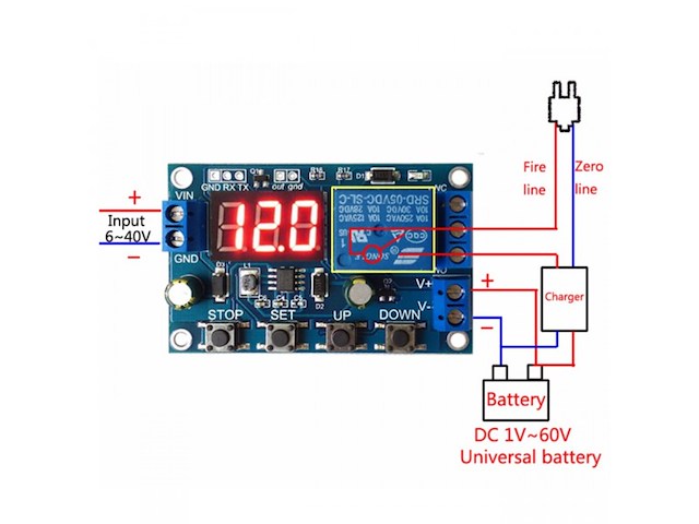
Prenaponska i podnaponska zaštita podesiva 0-40V DC Modul detektuje napon i prikazuje ga na displeju. Ukoliko je napon viši ili niži od zadatog isključuje izlazni rele i uključuje žvučnu signalizaciju (alarm) koji može da se isključi džamperom na ploci i LED indikaciju plave boje. Karakteristike: - Napon napajanja: DC 6-40 V - Napon detekcije i kontrole: 0-60 V DC - Izlazni rele: 30VDC/220VAC - 10A - Rele: NO + NC kontakt (normalno otvoren + normalno zatvoren) - Statička struja: 20 mA - Potrošnja u radu: 50 mA - Dimenzije: 60 x 40 x 18 mm Voltage upper limit: UL1, voltage lower limit nL1, voltage upper limit greater than Voltage lower limit (UL1>nL1) U-1: Charging measurement: when the measured voltage is lower than the lower limit voltage, the relay will be pulled up; if the voltage is upper limit, the relay will be disconnected. U-2: Charge measurement time control: set the charge time (OP); when the measured voltage is lower than the lower limit voltage, the relay is closed, and then starts to count down the OP time, ends the timer, and the relay turns off; when the measured voltage is higher than the upper limit voltage , the relay is turned off. U-3: Discharge detection: when the measured voltage is lower than the lower limit voltage, the relay is disconnected, and when the upper limit voltage is exceeded, the relay is pulled; U-4: Discharge detection time control: set the discharge time (OP); when the measured voltage is higher than the upper limit voltage, the relay is closed, and then starts to count down the OP time, the timer ends, and the relay is disconnected; when the measured voltage is lower than the lower limit voltage When the relay is disconnected; U-5: Within the voltage range, the relay pulling force: when the measured voltage is between the upper and lower limits, the relay is pulled, and other conditions are open; U-6: The voltage exceeds the interval, relaypull: The measured voltage is lower than the lower limit voltage or higher than the upper limit voltage, the relay is pulled, and the relay is closed in other cases. Voltage detection range DC0--60V, suitable for various batteries below 60V, voltage measurement error ±0.1V. 2: Charge and discharge time (OP) range: 0-999 minutes. How to set parameters? 1. First, determine the requirements of the working model according to your own needs; 2. According to the working mode of the relay, in the main interface (when the module is powered on, the current operation mode will flash, the default U-1 mode, and then enter the main interface) press the SET button for 2 seconds and release it to enter the selection mode interface, UP, DOWN button to select the mode to be set (U-1~U-6); 3. After selecting the mode, suppose we have selected the U-1 mode and pressed the SET button to set the corresponding parameters. The parameter to be set will flash (UL1 voltage upper limit, nL1 voltage lower limit, OP conduction time), press the UP, DOWN keys to increase or decrease, you can press the key to increase or decrease quickly at any time, press the SET button to set the next parameter The current mode, the above process; 4. Set the parameters, then press and hold the SET button for 2 seconds to release, the current setting mode will flash, and then return to the main interface, the parameters are set successfully! 5. On the main interface, press the DOWN key to switch between voltage and time. Mode selection interface: long press the SET key to enter the mode selection interface, after setting, long press the SET key, then release to exit the mode selection interface and return to the main interface.

-
Mašine i alati chevron_right Ručni alat i rezervni delovi
P06 Highlights Contains the voltmeter, ammeter, power meter, USB interface for charging the digital products. Note 1.When you use the product, the module inputs and outputs to be isolated from ground. 2.USB output voltage is consistent with the module, not a fixed 5V output. When charging for digital equipment, make sure USB output voltage is 5V. 3.Some customers report: ?The module can not adjust the output voltage is always equal to the input voltage.? When you encounter this problem, please counterclockwise rotation of the ?voltage potentiometer? 10 laps or more, then use the module you can adjust the output voltage. Because the factory default output voltage of about 20V. Specifications 1.Input voltage range:5-36VDC 2.Output voltage range:1.25-32VDC adjustable 3.Output current: 0-5A 4.Output power: 75W 5.High efficiency up to 96% 6.Built in thermal shutdown function 7.Built in current limit function 8.Built in output short protection function 9.Input reverse polarity protection: None (if required, high current diode in series with the input). 10.L x W x H =68.2×38.8×15mm 11.Weight: 39g Application 1.Use as a step-down modules with overcurrent protection Usage: (1) Adjust the right button so that ?OUT? LED lighted, Digital meter shows the value of output voltage ,adjust the ?voltage potentiometer? so that the output voltage reaches the value you want. (2) Adjust the right button so that Digital meter shows the value of output current;Wire shorted output terminal, then adjust the ?current potentiometer? so that the output current reaches a predetermined overcurrent protection value. (For example, the Digital meter displays the current value of 4A, then you can use the module to a maximum current of 4A) (3) Connected to the load. 2.Use as a battery charger Usage (1) Make sure you need to charge the battery float voltage and charging current; (if lithium parameters 3.7V/2200mAh, then the float voltage is 4.2V, the maximum charging current 1C, ie 2200mA) (2)Under no-load conditions, adjust the ?Voltage potentiometer? so that the output voltage reaches the float voltage; (if to 3.7V rechargeable lithium battery, the output voltage can be adjusted to 4.2V) (3)Adjust the right button so that Digital meter shows the value of output current;Wire shorted output terminal, then adjust the ?current potentiometer? so that the output current reaches a predetermined Charging current value. (4)Charge turn lamp current factory default is 0.1 times the charging current; (Battery during charging current is gradually reduced, if the charge current setting is 1A, then when the charge current is less than 0.1A, blue lights turned off, the green light is on, which means that the battery is fully charged) (5)connected to the battery charge. (1,2,3,4 steps as: Output is unloaded, do not connect the battery) 3.Use as a LED constant current driver module Usage (1)Adjust the voltage potentiometer so that the output voltage reaches the value you want. (2)Adjust the right button so that Digital meter shows the value of output current;Wire shorted output terminal, then adjust the current potentiometer so that the output current reaches a predetermined LED operating current. (3)Connect LED, work. (1,2 steps as: Output is unloaded, do not connect LED) Voltmeter and ammeter calibration method Module with manual calibration function can correct display precision voltage and current, if you think the current voltage and current accuracy to meet the requirements, do not perform the following operations. (1) Output voltage calibration steps Step 1, adjust the right button so that ?OUT? LED lighted, Digital meter shows the value of output voltage; Press the right button for more than 2 seconds, release, Digital meter and ?OUT? LED flashes in synchronization so that you enter the output voltage calibration mode. Step 2, press the right button (normal speed), the voltage value is adding up a unit; Press the left button, minus a unit; Due to a unit is less than 0.1V, the minimum voltage display to 0.1V, so you need to continuously press 1-5 times to see the voltmeter change 0.1V, how many times voltmeter change 0.1V by pressing the key, depending on the current display voltage, the higher the voltage, the fewer the number of press. Step 3, press the right button for more than 2 seconds, release, to exit the output voltage calibration mode. All parameters set to automatically power down to save. (2) Input voltage calibration steps Step 1, adjust the right button so that ?IN? LED lighted, Digital meter shows the value of input voltage; press the right button for more than 2 seconds, release, Digital meter and ?IN? LED flashes in synchronization so that you enter the input voltage calibration mode. Steps 2 and 3, consistent with the output voltage calibration method. (3)Output current calibration steps Step 1, adjust the right button so that Digital meter shows the value of output Current. Press the right button for more than 2 seconds, release, Digital meter flashes in synchronization so that you enter the output current calibration mode. Step 2,Connected to the load, ammeter in series, adjust the right and left button to change the display of digital meter, so that is consistent with the ammeter display
-
Mašine i alati chevron_right Ručni alat i rezervni delovi
Modul koji moze mnogo toga da odradi kada je akumulator u pitanju. Moze da drzi ukljuceno ili iskljuceno rele u zadatim granicama, ukljuceno ili iskljuceno iznad/ispod zadatog napona, da se iskljuci kada se napuni akumulator itd... Ima mogucnost i serijske komunikacije. Kompletan opis rada je ispod na engleskom. Operating mode: Voltage upper limit: UL1, voltage lower limit nL1, the voltage upper limit is greater than the voltage lower limit (UL1> nL1) U-1: Charging measurement: When the measured voltage is lower than the lower limit voltage, the relay pulls above; the upper limit voltage, the relay is disconnected. U-2: charge measurement time control: set the charging time (OP); when the measured voltage is lower than the lower limit voltage, the relay pull, and then start the countdown OP time, the end of the timer, the relay off; when the measured voltage is higher than the upper limit voltage , The relay is disconnected. U-3: Discharge detection: When the measured voltage is lower than the lower limit voltage, the relay is off, above the upper limit voltage, the relay pulls; U-4: discharge detection time control: set the discharge time (OP); when the measured voltage is higher than the upper limit voltage, the relay pull, and then start the countdown OP time, the end of the timer, the relay off; when the measured voltage below the lower limit voltage , The relay is disconnected; U-5: voltage in the range, the relay pull: when the measured voltage between the upper and lower limits, the relay pull, the other circumstances open; U-6: voltage outside the interval, the relay pull: the measured voltage below the lower limit voltage or higher than the upper limit voltage, the relay pull, the other case the relay is off. Product parameters: 1: Power supply voltage: DC6--40V, voltage detection range DC 0--60V, suitable for less than 60V of the various batteries, voltage measurement error ± 0.1V. 2: charge and discharge time (OP) range: 0 - 999 minutes. How do I set parameters? First, according to their needs, to determine the requirements of the work model; According to the working mode of the relay, in the main interface (when the module is powered on, it will flash the current mode of operation, the default U-1 mode, and then enter the main interface) press the SET button for 2 seconds and then release, enter the selection Mode interface, UP, DOWN button to select the mode to be set (U-1 ~ U-6); After selecting the mode, assume that we have selected the U-1 mode and press the SET button to set the corresponding parameter. The parameter to be set will flash (UL1 voltage upper limit, nL1 voltage lower limit, OP conduction time), press UP, DOWN Key to increase or decrease, you can always press the key to quickly increase or decrease, press the SET button to set the current mode of the next parameter, the process above; Set the parameters, and then press the SET button for 2 seconds to release, the current setting mode will flash, and then return to the main interface, set the parameters of success! In the main interface, press the DOWN key to achieve voltage and time switching. Mode selection interface: press the SET button for a long time to enter the mode selection interface, set the finished, a long time press the SET button and then release the exit mode selection interface, back to the main interface. Additional features: Data upload: through the serial port to achieve data upload, interval 1s upload a voltage and run time, easy to post-data analysis; Serial port settings parameters: You can set the mode and parameters through the serial port, more convenient; An extra signal output, when the relay to meet the conditions, the output high, the other output low. Serial port control (TTL level communication) Communication standard: The baud rate is 115200 bps Data bits: 8 Stop bit: 1 Check digit: none Flow control: none Serial command: `U-1`: Operating mode (range U-1 to U-6) `000`: 0 - does not enable timing function, non-0 - enable timing function (range 001 to 999) `Dw02.9`: Set the lower limit voltage `Up10.1`: set the upper limit voltage (range 00.0V ~ 99.9V) `Get`: Get the current settings `On`: Allows the relay to turn on `Off`: Always turn off the relay `Start`: start uploading data `Stop`: stop uploading data The above command can be any combination of two, need to be separated by commas Such as: `dw02.9, up10.1` set the lower limit voltage 02.9V upper limit voltage 10.1V Upload Status: Test Voltage + On Time + Status `00.0V, 00: 00: 00, OP r n` 00.0V: Measured voltage 00:00:00: Relay on time Status: OP relay on, CL relay off STOP key function expansion: Relay enable mode: ON: OP conduction time, the relay allows conduction; OFF: The relay is disabled and is always off; Press the STOP button on the main interface to switch between ON and OFF, the current status will flash, and then return to the main interface. (This function is an emergency stop function, a key to disconnect the relay) Sleep mode: C-P sleep mode: within five minutes, without any operation, the digital tube automatically shut down the display, the program normal operation; O-d normal mode: digital tube is always open display; Press and hold the STOP button for 2 seconds to release, to achieve C-P and O-d state of the switch, the current state will flash, and then return to the main interface.
-
Mašine i alati chevron_right Ručni alat i rezervni delovi
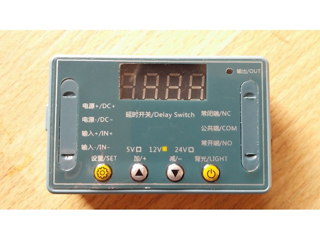
P14 Product Features: Wide voltage power supply (6 ~ 30V) supports micro USB 5.0V power supply, easy to use; The interface is clear and simple, powerful, easy to understand, meet almost all your needs; There is a key stop function (STOP key), with reverse polarity protection, reverse polarity does not burn; Increase the sleep mode, it enables, without any operation within 5 minutes, turn off the monitor automatically; any key to wake up; You can set a different OP, CL, LOP parameters, which are independent of each other, were saved; All setup parameters are saved automatically power down. Product parameters: Operating voltage: 6--30V support micro USB 5.0V power supply The trigger source: high trigger (3.0V-24V) signal with no common ground system to improve anti-jamming capability of the system (also self-shorting common ground) Output capability: You can control the DC or AC within 30v 5A within 220v5A Quiescent Current: 20mA Operating Current: 50mA Timing range: 0.1 seconds -999 minutes continuously adjustable; Availability: more than 10 million times Working temperature: -40-85 Celsius ; size: 6.2 * 3.8 * 1.7cm with optocoupler isolation, enhanced anti-jamming capability, industrial grade circuit boards, set the parameters after power failure memory forever. Special Note: The relay outputs are passive contact, uncharged output to control a line-off role. Product Manual: Operating mode: P1: After the trigger signal, the relay is turned OP time, and then disconnect; in the OP time, as follows P1.1: Invalid signal triggered again P1.2: Re-timing signal is triggered again P1.3: Reset signal is triggered again, the relay off, stop the clock; P-2: to the trigger signal, the relay after time off CL, OP relay conduction time, after the counting is finished, disconnect relay; P3.1: After the trigger signal to the relay turned OP time, relay off CL time, then the operation cycle, to signal to the relay off, stop the clock once again within the loop; cycles (LOP) can be set; P3.2: After power without triggering signal, the relay is turned OP time, relay off CL time, cycle the operation; cycles (LOP) can be set; P-4: signal holding function if there is a trigger signal timing is cleared, the relay remains on; when the signal disappears, after timing OP disconnect relay; timer period, then there is a signal, the timing is cleared; Timing setting: After setting the parameter values in the mode selection screen by a short press STOP button, select the time range; XXX decimal point bits, timing range: 1 second to 999 seconds XX.X decimal point in ten, Timing range: 0.1 seconds to 99.9 seconds X.X.X. decimal full brightness, Timing range: 1 minute to 999 minutes For example, you want to set up OP is 3.2 seconds, then move the decimal point to ten, the digital display 03.2 Parameter Description: OP-time, CL off time, LOP cycles (1-999 times, `---` represents infinite loop) These parameters are independent of each other, but each of these common mode parameters, for example, P1.1 set OP-time is 5 seconds, the user wants to switch to P1.2 mode, then enter P1.2 set the appropriate parameters, OP It will be five seconds; In the main interface (display 000) Press SET button will display OP (CL, LOP) and the corresponding time XXX; If only OP mode (such as the mode P1.1, P1.2, P1.3) time, then press SET button will display only the OP and the corresponding time; If the pattern has OP, CL, LOP (such as the mode P3.1, P3.2) then press the SET button OP and the corresponding time, CL and the corresponding time, LOP and the corresponding number will be displayed; In the set mode, the main interface parameters by a short press the SET button can easily see the current mode set in, very convenient! Parameter Settings: First, determine the operating mode of the relay; The mode of operation of the relay, in the main interface (when the module is powered on, flashes the current work mode (P1.1 default mode), then enter the main interface) `long press SET button for 2 seconds after the release `to enter mode selection screen by press UP, DOWN buttons to select the mode to be set (P1.1 ~ P-4); After selecting the mode to be set (for example, P3.2) Press SET key to set the appropriate parameters, then the parameter to be set flashes (OP-time, CL off time, LOP cycles ( `- - `represents infinite loop)) by UP, DOWN to adjust the value, support long press (rapid increase or decrease) and press (increase or decrease one unit); setting the parameter value by a short press STOP button to select the decimal point position, select time range (corresponding time of 0.1 seconds to 999 minutes); short press sET key to set the next parameter of the current mode, the process above; After setting the parameters of the selected mode is good, press the SET button for 2 seconds after release, currently set mode will flash, and then return to the main screen, set the parameters of success is very simple! The main interface: In the relay does not work status display `000` (no decimal point), with a decimal point under relay state, very clear! Mode selection screen: Long press SET to enter, after setting is completed, press SET key to exit and return to the main interface is very simple! STOP key functions: Relays enable mode: ON: inner OP-time relay allows conduction; OFF: relay prohibit conduction is always closed; In the main interface, short press the STOP button to switch between ON and OFF, the current in which the state will flash, and then return to the main screen. (This feature is an emergency stop function, a key disconnect relay closed) Sleep mode: C-P Sleep mode: five minutes without any operation, the digital display automatically turns off, the normal operation of the program; O-d normal mode: digital display always open; Press STOP button for two seconds after the release, to switch C-P and O-d state, in which the current state of flashes and then return to the main screen.
-
Mašine i alati chevron_right Ručni alat i rezervni delovi
P01 Battery charge and discharge module integrated voltmeter undervoltage and overvoltage protection timing charge and discharge with communication function Features: 1. Battery charge and discharge intelligent control 2. You can set the charge and discharge time 3. With serial communication function, real-time monitoring of the working status of the relay through the serial port 4. Additional signal output, when the relay to meet the conditions, the output high, you can control other equipment 5. A key emergency stop function (STOP button), with reverse protection, reverse does not burn Specifications: 1: Power supply voltage: DC 6--40V, voltage detection range DC 0--60V, suitable for less than 60V of the various batteries, voltage measurement error ± 0.1V 2: charge and discharge time (OP) range: 0 - 999 minutes Size: 5.9x3cm/2.32x1.18inch 1.Battery charge and discharge intelligent control; 2. You can set the charge and discharge time; 3. With serial communication function, real-time monitoring of the working status of the relay through the serial port; 4. Additional signal output, when the relay to meet the conditions, the output high, you can control other equipment. 5. A key emergency stop function (STOP button), with reverse protection, reverse does not burn. Operating mode: Voltage upper limit: UL1, voltage lower limit nL1, the voltage upper limit is greater than the voltage lower limit (UL1> nL1) U-1: Charging measurement: When the measured voltage is lower than the lower limit voltage, the relay pulls above; the upper limit voltage, the relay is disconnected. U-2: charge measurement time control: set the charging time (OP); when the measured voltage is lower than the lower limit voltage, the relay pull, and then start the countdown OP time, the end of the timer, the relay off; when the measured voltage is higher than the upper limit voltage , The relay is disconnected. U-3: Discharge detection: When the measured voltage is lower than the lower limit voltage, the relay is off, above the upper limit voltage, the relay pulls; U-4: discharge detection time control: set the discharge time (OP); when the measured voltage is higher than the upper limit voltage, the relay pull, and then start the countdown OP time, the end of the timer, the relay off; when the measured voltage below the lower limit voltage , The relay is disconnected; U-5: voltage in the range, the relay pull: when the measured voltage between the upper and lower limits, the relay pull, the other circumstances open; U-6: voltage outside the interval, the relay pull: the measured voltage below the lower limit voltage or higher than the upper limit voltage, the relay pull, the other case the relay is off. Product parameters: 1: Power supply voltage: DC6--40V, voltage detection range DC 0--60V, suitable for less than 60V of the various batteries, voltage measurement error ± 0.1V. 2: charge and discharge time (OP) range: 0 - 999 minutes. How do I set parameters? 1. First, according to their needs, to determine the requirements of the work model; 2. According to the working mode of the relay, in the main interface (when the module is powered on, it will flash the current mode of operation, the default U-1 mode, and then enter the main interface) press the SET button for 2 seconds and then release, enter the selection Mode interface, UP, DOWN button to select the mode to be set (U-1 ~ U-6); 3. After selecting the mode, assume that we have selected the U-1 mode and press the SET button to set the corresponding parameter. The parameter to be set will flash (UL1 voltage upper limit, nL1 voltage lower limit, OP conduction time), press UP, DOWN Key to increase or decrease, you can always press the key to quickly increase or decrease, press the SET button to set the current mode of the next parameter, the process above; 4. Set the parameters, and then press the SET button for 2 seconds to release, the current setting mode will flash, and then return to the main interface, set the parameters of success! 5. In the main interface, press the DOWN key to achieve voltage and time switching. Mode selection interface: press the SET button for a long time to enter the mode selection interface, set the finished, a long time press the SET button and then release the exit mode selection interface, back to the main interface. Additional features: 1. Data upload: through the serial port to achieve data upload, interval 1s upload a voltage and run time, easy to post-data analysis; 2. Serial port settings parameters: You can set the mode and parameters through the serial port, more convenient; 3. An extra signal output, when the relay to meet the conditions, the output high, the other output low. Serial port control (TTL level communication) Communication standard: The baud rate is 115200 bps Data bits: 8 Stop bit: 1 Check digit: none Flow control: none Serial command: `U-1`: Operating mode (range U-1 to U-6) `000`: 0 - does not enable timing function, non-0 - enable timing function (range 001 to 999) `Dw02.9`: Set the lower limit voltage `Up10.1`: set the upper limit voltage (range 00.0V ~ 99.9V) `Get`: Get the current settings `On`: Allows the relay to turn on `Off`: Always turn off the relay `Start`: start uploading data `Stop`: stop uploading data The above command can be any combination of two, need to be separated by commas Such as: `dw02.9, up10.1` set the lower limit voltage 02.9V upper limit voltage 10.1V Upload Status: Test Voltage On Time Status `00.0V, 00:00: 00, ON \ r \ n` 00.0V: Measured voltage 00:00:00: Relay on time Status: OP relay on, CL relay off STOP key function expansion: Relay enable mode: 1. ON: OP conduction time, the relay allows conduction; 2. OFF: The relay is disabled and is always off; Press the STOP button on the main interface to switch between ON and OFF, the current status will flash, and then return to the main interface. (This function is an emergency stop function, a key to disconnect the relay) Sleep mode: 1. C-P sleep mode: within five minutes, without any operation, the digital tube automatically shut down the display, the program normal operation; 2. O-d normal mode: digital tube is always open display; Press and hold the STOP button for 2 seconds to release, to achieve C-P and O-d state of the switch, the current state will flash, and then return to the main interface.
-
Mašine i alati chevron_right Ručni alat i rezervni delovi
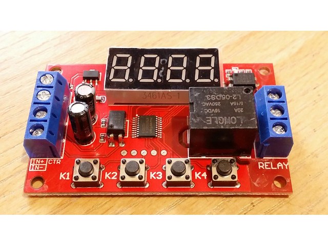
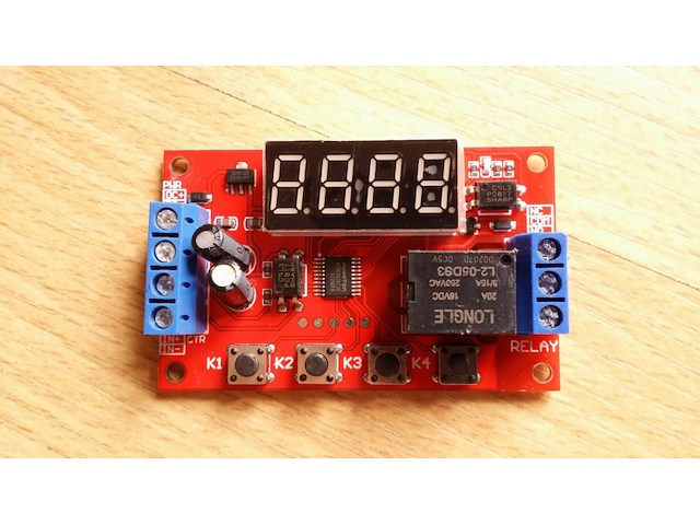
P04 The multi-function relay control module is specially designed for users with many different needs. It adopts a microcontroller as the main control unit and presets 32 kinds of functions, and users can use corresponding specific functions according to actual needs. It can be applied to water pump control, motor control, lamp strip control, solenoid valve control, etc. 1. New upgrade, the module function is increased to 32 kinds, to meet more application needs. 2. The power supply anti-reverse function will not damage the module due to wrong power supply. 3. Timing accuracy to 0.01 seconds timing. 0.1 seconds (minimum) ~ 999 minutes (maximum) optional 4. Low power consumption power saving setting, you can turn off the display area. Product parameters: Product Name: Multi-function time delay relay Relay V number: DC5V/12V/24V optional Input voltage: 5V version: DC5V power supply; 12V version: DC12V power supply; 24V version: DC24V power supply Output load: within 30V DC, maximum 10A. Within 250V, maximum 5A. Trigger signal: 5V version (high level: 5V); 12V version (high level: 12V), 24V version (high level: 24V) The low level is 0V. Quiescent current: 20mA Working current: 60mA Working temperature: -25℃-85℃ Power-off memory: Yes Product weight: ≈26g, product size: 65* 34.3 * 17.5 (MM L*W*H) The manual measurement is for reference only, the actual size is subject to the actual product Product Features: Wiring port description: DC+ Input DC power supply positive DC- Input DC power supply negative IN+ signal input positive IN- signal input negative NO relay normally open interface, the relay is short-circuited with COM when it is engaged, and it is suspended when not engaged; COM relay common terminal interface NC relay normally closed terminal interface, when the relay is not pulled in, it is short-circuited with COM, and it is left floating when pulled in; Instructions for use: Working mode (32 kinds): P-11: In jog mode, there is signal pull-in and no signal disconnect. P-12: Self-locking mode, the state of the relay reverses once after each trigger. P-13: After triggering, the relay will pull in and disconnect after delaying A time; the trigger will be invalid during the delay. P-14: After triggering, the relay will pull in, and it will be disconnected after the delay of A time; the trigger will be re-timed during the delay. P-15: After triggering, the relay will pull in, and it will be disconnected after the delay time A; during the delay time, the accumulated timer will be triggered. P-16: After triggering, the relay will pull in and disconnect after delaying time A; during the delay, a reset will be triggered (relay disconnected). P-17: After triggering, the relay pulls in for the duration of the signal, the input signal disappears, and then disconnects after the delay of A time; during the delay time, the relay is triggered again to keep the pull in, and the timing stops until the last signal disappears, delay A time Then disconnect. P-18: The relay will pull in immediately after power-on, and it will be disconnected after a delay of A second; until the next power-on. P-21: Give the signal, the relay will pull in after the delay of A time. P-22: Give a continuous signal, after the time exceeds A, the relay will pull in; when the signal disappears, the relay will open. P-23: When the signal disappears for more than A time, the relay pulls in; when there is a signal, the relay disconnects. P-24: Give a continuous signal. After the time exceeds A, the relay will pull in; when the signal disappears for more than time A, the relay will open. P-25: Give a continuous signal, the relay pulls in after exceeding A time; give a continuous signal again, the relay turns off after exceeding A time P-26: Give a signal, the relay will disconnect after A time pull-in; after the signal disappears, the relay will stop after A second pull-in. P-27: There is a pulse signal (rising edge or falling edge), the relay is disconnected, there is no pulse signal, the relay pulls in after the delay of A time (continuous high level or continuous low level are considered as no pulse). P-28: After power on, the relay will pull in after the delay time A until power off. The P-31: After power-on, the relay pulls in time A and turns off time B, in an infinite loop; power off stops. P-32: There is a continuous signal, the relay pulls in A time, disconnects B time, infinite loop; the signal disappears, and the loop is terminated. P-33: Give a signal once, the relay pulls in A time, disconnects B time, infinite loop; give another signal to terminate the loop. P-34: After power-on, the relay pulls in after the delay time A, and disconnects after pulling in the time B. P-35: Give a signal, after the delay time A, the relay pulls in and pulls off after the time B pulls in. P-36: Continuous signal is given. After the time A is exceeded, the relay is switched on and disconnected after the time B is switched on; the signal disappears, the timing is cleared, and the relay is turned off. P-37: There is a signal, the relay will be automatically disconnected after the A time is closed, and the B time will be counted after the disconnection. The signal trigger is invalid during the A+B time. P-38: There is a signal, the relay will be automatically disconnected after the time of pull-in A, after the time B is counted after the disconnection, it will be automatically disconnected after the time of pull-in A again. The P-41: The signal does not act; the signal disappears and triggers; the relay absorbs and merges after a delay of A time to disconnect. P-42: The signal disappears. After the delay time A, the relay pulls in; after the delay time B, the relay disconnects. P-43: The signal disappears. After the disappearance exceeds the time A, the relay pulls in; after delaying the time B, the relay opens. P-44: After power-on, the relay pulls in time A and turns off time B; after the cycle C times, the relay turns off and stops. P-45: No action after power on; after the signal is given, the relay pulls in the A time and disconnects the B time; the relay is turned off and stopped after C cycles; when the signal is given, it is executed again. P-46: After the signal is given more than A times, the relay pulls in; keeps pulling in; the power stops. P-47: After the signal exceeds A times, the relay pulls in; when it pulls in for B time, it is disconnected. P-48: During the C time, after continuously giving the signal more than A times, the relay will disconnect and stop after B time. Description table of the position of the decimal point and the time unit it represents: x.xx Decimal point is in the hundreds place, time range 0.01~9.99 seconds xx.x decimal point is in the tenth place, time range 0.1~99.9 seconds xxx has no decimal point, time range is 1~999 seconds xxx. The decimal point is in single digits, the time range is 1~999 minutes Turn off the display: In the non-setting state, press the K4 key to turn off the display, then press it again to turn on. Description of working parameter setting: Hold down the K1 key without letting go, after 2 seconds the display shows P-xx, press K2 and K3 to change the working mode. After selecting the working mode, short press K1 to enter the A time setting, the screen displays Axxx, then press K2 and K3 to modify the A time parameters, K2 and K3 key short press plus or minus 1, long press to quickly add and subtract 10, Press the K4 key to set the position of the decimal point. After setting the A time, press the K1 key to set the B time, the screen displays bxxx, then press the K2 and K3 keys to modify the B time parameters, K2 and K3 keys short press plus or minus 1, long press to quickly add and subtract 10, Press the K4 key to set the position of the decimal point. After setting the B time, (if the mode has the C cycle number parameter), then press the K1 key to set the C cycle number, the screen displays Cxxx, then press the K2 and K3 keys to modify the C cycle number parameter, K2 and K3 keys Short press to increase and decrease by 1, long press to increase and decrease by 10. After setting, press the K1 key once to exit the setting state and save all parameters.
-
Mašine i alati chevron_right Ručni alat i rezervni delovi
K15 Multi-mode delay time relay module 32 modes of pulse delay time delay time delay high precision programmable optocoupler isolation 5 v12v24v optional The multi-function relay control module is specially designed for users with various requirements. It adopts the microcontroller as the main control unit with 32 functions preset. Users can use the corresponding specific functions according to the actual requirements. Can be used in water pump control, motor control, lamp belt control, solenoid valve control and so on. 1. New upgrade, increasing the number of module functions to 32, to meet more application requirements. 2. Anti-backconnection function of power supply, which will not damage the module due to wrong power supply. 3. Timing accuracy to 0.01 second. 0.1 seconds (minimum) ~999 minutes (maximum) optional 4.. Low power saving Settings, you can turn off the display area. Product parameters: Commodity name: Multi-function delay relay Relay V number: DC5V/12V/24V optional Input voltage: 5V Version: DC5V power supply; 12V version: DC12V power supply; 24V version: DC24V power supply Output load: dc 30V, Max 10A. Ac 250V, maximum 5A. Trigger signal: 5V version (high level: 5V); Both 12V (HIGH level: 12V) and 24V (high level: 5V) low levels are 0V. Static current: 20mA Operating current: 60mA Operating temperature: -25℃-85℃ Power off memory: Yes Product weight: ≈26g, product size: 65 x 34.3 X 17.5 (MM) Manual measurement is for reference only. The actual size is subject to the material object Warm tips: 1. Please select the required V version (according to the relay identification difference above, the relay is 5V instant 5V version) to avoid wrong purchase. 2. The output of relay is passive contact without current output to control the on-off effect of a line. 3. Please input the trigger voltage strictly according to the selected version Instructions for use: Working mode (32 kinds) : P-11: Inching mode with suction and no disconnection. P-12: Self-locking mode, and the relay state is reversed once after each trigger. P-13: When triggered, the relay pulls in and disconnects after A time delay; Invalid trigger during delay. P-14: When triggered, the relay pulls in and disconnects after A time delay; Retiming is triggered during a delay. P-15: When triggered, the relay pulls in and disconnects after A time delay; Accumulative timing is triggered during delay. P-16: When triggered, the relay pulls in and disconnects after A time delay; Trigger reset (relay disconnection) during delay. P-17: When triggered, the relay pulls in during the signal duration, the input signal disappears, and the relay is disconnected after A time delay; During the delay, the relay is triggered again to keep the suction, and the timing stops until the last signal disappears, and the relay is disconnected after the delay of time A. P-18: After the power is switched on, the relay will pull in immediately and disconnect after A second delay; Until the next power cut. P-21: Signal feed, relay suction after delay A time. P-22: Give the continuous signal. After A time, the relay pulls in; The signal disappears and the relay disconnects. P-23: When the signal disappears beyond time A, the relay pulls in; There is a signal, the relay is off. P-24: Give the continuous signal. After A time, the relay pulls in; When the signal disappears beyond time A, the relay is disconnected. P-25: Give the continuous signal. After A time, the relay pulls in; Give the continuous signal again, after A time, the relay is disconnected P-26: Signal is given and the relay is disconnected after absorbing A time; After the signal disappears, the relay pulls in again for A second and then stops P-27: the relay with pulse signal (rising edge or falling edge) is disconnected, and there is no pulse signal. The relay will be absorbed after A time delay (both continuous high level and continuous low level are considered to have no pulse). P-28: After power on, the relay will pull in after delay time A until power off. P-31: After power on, the relay pulls in time A and disconnects time B, infinite cycle; The power is off. P-32: With continuous signal, the relay pulls in A time, disconnects B time, infinite cycle; The signal disappears and the loop is terminated. P-33: Give A signal, the relay pulls in A time, disconnects B time, infinite cycle; Give the signal one more time to stop the loop. P-34: After power on, the relay will pull in after delay time A, and disconnect after pull in time B. P-35: Signal is given once. After delay of time A, the relay pulls in and shuts off after time B. P-36: Give the continuous signal. After A time, the relay will pull in and disconnect after B time. Signal disappeared, time reset, relay disconnected. P-37: There is A signal. The relay will automatically disconnect after it pulls in time A, and then timing time B after it is disconnected. The signal trigger will be invalid within time A+B. P-38: There is A signal. The relay will automatically disconnect after absorbing A time, and then timing B time after disconnecting, and automatically disconnect after absorbing A time again. P-41: No action on signal; Signal vanishing trigger; The relay is disconnected after absorbing the delay time of A. P-42: the signal disappears and the relay pulls in after A time delay; The relay disconnects after B time delay. P-43: The signal disappears, and the relay pulls in after the disappearance exceeds time A; The relay disconnects after B time delay. P-44: After power on, the relay attracts time A and disconnects time B; The relay disconnects and stops after C cycles. P-45: No action after power on; After giving the signal, the relay attracts A time and disconnects B time; The relay disconnects and stops after C cycles. Give the signal, then execute again. P-46: When the signal is given more than A times, the relay pulls in; Keep the suction; The power is off. P-47: When the signal is given more than A times, the relay pulls in; Disconnect after suction B time. P-48: In C time, after continuous signal feeding for more than A times, the relay will disconnect and stop after absorbing B time. Table showing the position of the decimal point and the unit of time it represents: The decimal point is in the hundreds place, and the time range is 0.01~9.99 seconds Xx. X decimal point in ten place, time range 0.1~99.9 seconds XXX has no decimal point and the time range is 1-999 seconds XXX. The decimal point is in one place and the time range is 1-999 minutes Turn off display: In non-set state, press K4 to turn off the display screen, then press again to open it again. Description of working parameters setting: Hold down the K1 key and hold it until p-XX appears on the screen 2 seconds later. Press K2 and K3 to change the working mode. After selecting the working mode, press K1 to enter the time setting of A, and Axxx is displayed on the screen. At this time, press K2 and K3 to modify the time parameters of A, press K2 and K3 to add and subtract 1 for short, long to add and subtract 10 for fast, and press K4 to set the position of the decimal point. After setting time A, press K1 to set time B. BXXX is displayed on the screen. At this time, press K2 and K3 to modify time parameters of B; press K2 and K3 to add or subtract 1 for short; press K4 to add or subtract 10 for long; and press K4 to set the position of the decimal point. After setting the B time (in the case that the mode has C cycle number parameter), press K1 to set the C cycle number, and the screen shows Cxxx. At this time, press K2 and K3 to modify the C cycle number parameter, press K2 and K3 to add or subtract 1 for short, and press long to add or subtract 10 for fast. After setting, press the K1 key one last time to exit the setting state and save all parameters. Description of wiring port: DC+ input DC power positive pole DC- input DC power negative pole IN+ signal input positive pole IN- negative input terminal NO relay always start interface, relay suction and COM short connected, not closed suspension; COM relay common end interface Normally closed end interface of NC relay. When the relay fails to suck, it is short connected with COM. When the pull, it is suspended.
Istorija cene
Naziv oglasa
Početna cena
Najveća cena
Najniža cena
Nema podataka o istoriji cene

Pretraga: " "
Uspešno ste zapratili pretragu.
Sve zapraćene pretrage možete videti u
korisničkom panelu.