

Pratite promene cene putem maila
- Da bi dobijali obaveštenja o promeni cene potrebno je da kliknete Prati oglas dugme koje se nalazi na dnu svakog oglasa i unesete Vašu mail adresu.
126-138 od 138 rezultata
Prati pretragu "Čase"
Vi se opustite, Gogi će Vas obavestiti kad pronađe nove oglase za tražene ključne reči.
Gogi će vas obavestiti kada pronađe nove oglase.
Režim promene aktivan!
Upravo ste u režimu promene sačuvane pretrage za frazu .
Možete da promenite frazu ili filtere i sačuvate trenutno stanje
Aktivni filteri
-
Izbačen Sajt
www.giftshop.rs

-
Mašine i alati chevron_right Ručni alat i rezervni delovi
Specijalna silikonska boja u spreju otporna na visoke temperature. Pogodna je za upotrebu na izduvnim sistemima, hladnjacima i ventilima na automobilima, radijatorima, dimnjacima, grejnim telima i rernama. Ne koristiti bilo kakve osnovne i zaštitne boje pre nanošenja spreja pošto oni imaju manju otpornost na temperaturu. Boja postiže svoju konačnu čvrstoću nakog prvog zagrevanja na 150-200°C u trajanju od najmanje 2 sata. Podnosi temperature do 600°C. Boca od 400ml pokriva površinu od 1,5-2m2 u zavisnosti od boje farbe. Otporan na prašinu posle 10 minuta, na dodir posle 20 minuta a potpuno sušenje se postiže u roku od 24 časa. Boja: aluminijum.

-
Mašine i alati chevron_right Ručni alat i rezervni delovi
Bluetooth pojacalo snage 2x100W u kucistu. Napaja se sa 5-27V (preporucuje se 24V 5A), na izlaze se zakace zvucnici a na telefonu, tabletu pronadje uredjaj preko bluetooth-a i preko njega pusta zvuk. Poseduje potenciometar za ukljucenje uredjaja, pojacavanje i smanjivanje zvuka. Pored bluetooth povezivanja moze se vezati na AUX ulaz 3.5mm dzekom direktno na telefon, mp3 plejer ili nesto slicno. Obratiti paznju na polaritet napajanja, centralni vod na dzeku je plus a oklop minus. AUX+ bluetooth input 2-in-1 HIFI level with filter 2x100W bluetooth digital amplifier board Attention! The case needs to be assembled by yourself. Free screwdriver. This product is full of materials, featuring high performance and high performance price, especially for HIFI music power amplifier with high power and high fidelity. TPA3116D2 is a type D amplifier IC launched by TI company, which has very high index parameters. The maximum modulation frequency is 1.2MHZ, and the high power output distortion is less than 0.1%. The red and gray ring inductors are specially designed for digital power amplifiers, featuring low loss, high bandwidth and high fidelity. The 684 film capacitor is a special capacitor for audio amplifier, which has the characteristics of low loss, high bandwidth and high fidelity. With AUX and bluetooth two audio source input mode, two in one. Potentiometer adjust volume, with switch, easy to control volume, very suitable for DIY speakers. Copper DC female head, fence terminal, withstand large current, no heat, no damage to the line, good wiring, not easy to short circuit. 5.0 bluetooth version, higher transmission efficiency, longer transmission distance. Notes for use: the power switch on the board is standby switch, and the machine is in standby state with low power consumption after the switch is turned off. To completely turn off the power or to remove the DC plug on the machine for a long time, it is ok.

-
Mašine i alati chevron_right Ručni alat i rezervni delovi
P14 3Series Of 12.6V 25A W/Balance 18650 Li-ion Lithium Battery PCB Protection Board Description: Of the products are sold in this shop contains some electronic technical,if you don`t understand or not sure whether to apply to your product,please consult customer service first,the customer before buying,please learn more about our page description parameters,lest cause unnecessary trouble.Thank you very much!(caution for beginners). Note: This can not be used in lithium iron phosphate battery protection board,hernia lamp, hand electric drill battery, cannot be used for electric fish electromechanical ChiZu,electric bicycle batteries,car batteries, children (4 a) more than 775 motor,fisheye 1 w LED lamp,used for the combined purchase customers please note! 3 for discharge products above A current,the discharge multiplier of the battery shall be over 3C. Multiplier calculation formula:1C battery, 2000 capacity = 2AH*1=2A working current.3C multiplier batteries,2000 capacity is equal to 2AH*3=6A working current.In use,the battery will heat up or the battery multiplier is not applicable.In this case,it cannot be used for a long time and the battery will be damaged quickly. Applicable to the following products: Massager battery pack,LED lamp backup power supply,12V electronic products,solar lamp battery pack,monitoring standby power supply,and other products. Properties: Model:HX - 3 s - FL25A - A. Overcharge pressure range:4.25-4.35v plus or minus 0.05v. Overvoltage range:2.3-3.0v plus or minus 0.05v. Maximum working current:20-25a (heat dissipation attention). Working temperature:- 40 - 50 ℃. Upper instantaneous current:35-40a. Storage conditions:- 40 - 80 ℃. Static current:less than 30uA. Useful life:over 30,000 hours. Resistance:less than 100 m Ω. Short circuit protection:can protect, delay self - recovery. Equilibrium current:45 ma. Charging voltage:12.6v -13V. Description of test point:if S1 S2 shortens P P-,it will output voltage, indicating that all MOS are protected normally.A normally open temperature detection can extend the temperature protection effect.

-
Mašine i alati chevron_right Ručni alat i rezervni delovi
Kit komplet - trcece svetlo kruzno sa NE555 i CD4017 kolima, nesto kao bacanje kocke, lutrija. .. Suite parameters: Kit Model: LUCKY-10 Supply voltage :3-5V Dimensions: 58 * 58mm Board FR-4 military grade A material 1. Many soldering pads do not come off easily 2 becomes less likely to occur from the bending (refer to the non-human case resulting bending), poor sheet with time and changes in the environment arising from bending. 3. Impedance more stable and reliable Plate tolerance and stability of some of the parameters A material was very powerful interests in relative to some other sheet metal price of money. The function play: Wheel of Fortune is to predict the rotation of the disc to stop, and in the end will stop in which the position of the tool. Also can be used to estimate numbers game, electronic dice, lottery machine. Electronic Wheel of Fortune is in electronic way to reach the same functionality, this package of 10 LEDs configured in a circle, click the button, each LED sequence turns luminous, the flow speed is getting slower and slower and finally stopped at a only LED is no longer moving. The last shiny forecast that LED with players, said that `winning`. Circuit: The circuit is composed mainly by the pulse generator and a decimal counter circuit. Pulse generator by NE555 and peripheral components constitute a multivibrator, press the button S1 when Q1 conduction NE555 pin 3 output pulse, the CD4017 10 output of turns output high drive 10 LEDs turns luminous. The key is released, due to the presence of the capacitor C1, Q1 does not immediately turned off, with the C1 voltage decreased, Q1 of conduction program gradually weakened, 3 feet of the output pulse frequency slows, LED movement frequencies also will slower. Finally, when after the end of the C1 discharge. Q1 off NE555 3 feet longer output pulse LED stops moving. `Lottery` process completed. R2 determine the the LED movement speed, C1 decided to wait for a `lottery`.

-
Mašine i alati chevron_right Ručni alat i rezervni delovi
P04 Feature parameters: Working voltage: DC 24V Load Power: DC 0-30V 10A / AC 0-220V 10A Static current:15mA Working current:30mA Service life: 100 thousand times; Working temperatures: -40-85° Size: 65*8*18mm Package included: 1 pc Step 1: power on, Step 2: Press the SET key for a long time to enter the function selection, and display P1-P8. Press the SET key for a short time to switch between function 1 and function 8. Step 3: Press ADD to select T1 time unit, display the value (-0/1/2/3), and set T1 time unit. At this time, press ADD to switch between 0/1/2/3. . Time unit:-0: 0.1 second file, time range 0.1 second -9.9 seconds -1: 1 second file, time range 1 second -99 seconds -2: 1 minute, the time range is 1 minute -99 minutes -3: 1 hour, time range 1 small clock -99 hours Step 4: Press SET key to set T1 time and display T1. At this time, press ADD/Enter key to add and subtract time and display the numerical value (00). In case of functions 1, 2, 5 and 6, press the SET key to confirm saving, and the setting ends. If it is function 3, 4, 7, 8, enter the fifth step. Step 5: Press the SET key to set T2 time unit. Display `-0/1/2/3`, set T2 time unit, and press ADD key to switch between 0/1/2/3. . Time unit:-0: 0.1 second file, time range 0.1 second -9.9 seconds -1: 1 second file, time range 1 second -99 seconds -2: 1 minute, the time range is 1 minute -99 minutes -3: 1 hour, time range 1 small clock -99 hours Step 6: Press SET to set T2 time and display `T2`. At this time, press ADD/Enter to add and subtract time and display the numerical value (00). Step 7: Press SET key to set the cycle times and display `C-`. At this time, press ADD/Enter key to increase and decrease the cycle times and display the numerical value (00). If it is set to 0, it is infinite cycle. Step 8: Press the SET key to confirm the save.

-
Mašine i alati chevron_right Ručni alat i rezervni delovi
P04 Feature parameters: Working voltage: DC 12V Load Power: DC 0-30V 10A / AC 0-220V 10A Static current:15mA Working current:30mA Service life: 100 thousand times; Working temperatures: -40-85° Size: 65*8*18mm Package included: 1 pc Step 1: power on, Step 2: Press the SET key for a long time to enter the function selection, and display P1-P8. Press the SET key for a short time to switch between function 1 and function 8. Step 3: Press ADD to select T1 time unit, display the value (-0/1/2/3), and set T1 time unit. At this time, press ADD to switch between 0/1/2/3. . Time unit:-0: 0.1 second file, time range 0.1 second -9.9 seconds -1: 1 second file, time range 1 second -99 seconds -2: 1 minute, the time range is 1 minute -99 minutes -3: 1 hour, time range 1 small clock -99 hours Step 4: Press SET key to set T1 time and display T1. At this time, press ADD/Enter key to add and subtract time and display the numerical value (00). In case of functions 1, 2, 5 and 6, press the SET key to confirm saving, and the setting ends. If it is function 3, 4, 7, 8, enter the fifth step. Step 5: Press the SET key to set T2 time unit. Display `-0/1/2/3`, set T2 time unit, and press ADD key to switch between 0/1/2/3. . Time unit:-0: 0.1 second file, time range 0.1 second -9.9 seconds -1: 1 second file, time range 1 second -99 seconds -2: 1 minute, the time range is 1 minute -99 minutes -3: 1 hour, time range 1 small clock -99 hours Step 6: Press SET to set T2 time and display `T2`. At this time, press ADD/Enter to add and subtract time and display the numerical value (00). Step 7: Press SET key to set the cycle times and display `C-`. At this time, press ADD/Enter key to increase and decrease the cycle times and display the numerical value (00). If it is set to 0, it is infinite cycle. Step 8: Press the SET key to confirm the save.

-
Mašine i alati chevron_right Ručni alat i rezervni delovi
HVLP ručni pištolj za prskanje BORMANN Lite BPG8100 omogućava praktičan i svestran način farbanja u zatvorenom i na otvorenom. Uključuje HVLP tehnologiju koja obezbeđuje savršene potpuno podesive ventilatore za prskanje bez stvaranja dosadnih oblaka boje. Daje odličan konačni estetski rezultat, ekonomičnost i brzinu – prednosti neuporedivo bolje od farbanja četkama, valjcima itd. Može koristiti širok spektar materijala (kao što su lakovi i boje rastvorljive u vodi) i pokrivati širok spektar potreba. Ventilator se može podesiti da prska horizontalno, vertikalno ili u tankom okruglom snopu za lak pristup teško dostupnim mestima. Ima podešavanje količine boje za još bolje prilagođavanje i fleksibilnost u zavisnosti od materijala i upotrebe. Takođe ima odvojivu glavu koja olakšava njegovo čišćenje. U pakovanju dolazi i čaša za merenje viskoziteta kao i mlaznica: Φ 1.8/2.6 mm. Preuzmite uputstvo i tehničke specifikacije
-
Mašine i alati chevron_right Ručni alat i rezervni delovi
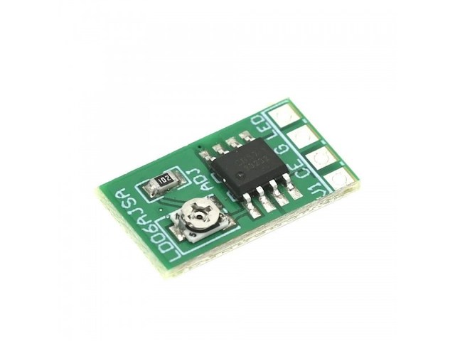
P17 Product parameters: 1. Working voltage: DC 2.8-6V (for 3V 3.3V 3.7V 4.5V 5V 6V LED driver) 2. Output current: 30-1500MA 3. Maximum output power: 9W Can drive 1-16 2.8-6V leds (Maximum current does not exceed 1.5A) 4. Current regulation: 1 through adjustable resistance; 2 Control chip temperature regulation through PWM signal Over LED current protection Operating temperature range Application 1: Wiring in accordance with the following figure, use a suitable screwdriver gently and slowly rotate the adjustable resistance. Application 2: Adjust the adjustable resistance to 0 ohms (or maximize the current according to Application 1) and then use the MCU output PWM signal to control the LED output current the frequency of the PWM signal should be less than 2KHz Product Description: LD06AJSA/B is a current regulation integrated circuit operating from an input voltage of 2.8V to 6V, the constant output current can be set up to 1.5A with an external resistor. The LD06AJSA/B consists of high precision reference voltage, amplifier, current mirror, etc. The on-chip power transistor and current sense block greatly reduce the external component count, which makes the LD06AJSA/B ideal for LED driver. When the CE pin is high, the input voltage is greater than 2.8V, and is larger than the LED forward voltage plus the required voltage drop, LD06AJSA/B functions normally to deliver constant current from the LED pin. The LD06AJSA/B adopts the temperature regulation instead of temperature protection function, the temperature regulation can make the LED being turned on continuously in case of high ambient temperature or high voltage drop. When the LD06AJSA/B junction temperature reaches about 135 ° C, the internal temperature regulation block reduces the LED current so that the junction temperature will not rise any more. This feature allows the users to maximize the use of the power handling capability of the chip, do not worry about the chip overheating and damage to the chip or external components. The LD06AJSA/B also has the chip enable function, which can shutdown the whole chip to limit the current consumption within 1uA. The LD06AJSA/B also adopts the over current protection block. When LED current approaches 1.9A(Typical), the over current protection block begins to function to prevent the LED current from increasing further.

-
Mašine i alati chevron_right Ručni alat i rezervni delovi
Opis Ručni nivelator pločica RUBI 60926 Ručni nivelator pločica RUBI 60926 Korisničke pogodnosti i osobine: Sa Rubi alatom Tile Regulator, profesionalni postavljač keramičkih pločica moći će brzo i precizno prilagoditi fugiranje koje se generiše pri postavljanju pločica, kako na zidovima tako i na podovima. RUBI Tile Regulator je posebno dizajniran za rad sa porcelanskim pločicama i pločicama velikog formata. Ovi materijali velikog obima su vrlo teški za podešavanje nakon što su postavljeni. Snaga dvostrukog lepljenja stvara mnogo otpora i korisnik mora uložiti veliki napor, pri čemu postoji rizik da se materijal ošteti. Kako bi olakšala ovaj proces, RUBI stavlja Tile Regulator na raspolaganje profesionalcima. Opremljen sa dve vakuumskih čaša prečnika 150 mm i pogodan za različite vrste površinskih završetaka. Regulator se pričvršćuje za dve različite pločice, jednu koja je upravo postavljena i drugu koja je prethodno postavljena. Kada se vakuumski čaše prikače za obe pločice, možemo podesiti veličinu fuge od 0 do maksimalno 1,5 inča. Tile regulator takođe omogućava prilagođavanje horizontalnog nivoa pločica od 0 do 0,78 inča i to na pločicama maksimalne težine od (100 kg). Važno je napomenuti da tile regulator ne zamenjuje, ni u kom slučaju, upotrebu razbojnica ili sistema za nivelisanje, jer je ovaj alat dizajniran da omogući jednostavno i brzo izvođenje manjih prilagođavanja koja bi se na pločicama manjeg formata inače vršila ručno, uz minimalan napor profesionalca za postavljanje keramičkih pločica. Za slučajeve u kojima je potrebno raditi sa vrlo velikim formatima, uvek se preporučuje upotreba dva tile regulatora. Na taj način će se postići mnogo brže i preciznije prilagođavanje postavljenog dela. Tehničke karakteristike: Dužina Širina Visina (ukupne dimenzije mašine) – 48 x 15 x 12 cm Neto težina bez ambalaže – 3,61 kg Bruto težina – 3,84 kg O brendu: Rubi mašine za sečenje keramike i keramičarski pribor se nalaze u samom vrhu keramičarske industrije. Rubi mašine su izbor za profesionalne majstore, zbog izuzetno preciznog reza i lakoće sa kojom mašina seče pločice. Kopmanija RUBI osnovana je 1951. godine, od strane braće Boada. Rubi mašine su danas prisutne u preko 120 zemalja, a logistički centar komanije se nalazi u Španiji. Tim Komerc kontakt: Telefon: 011 3 984 586 / 060 3 984 586 / 011 3 984 587 / 011 3 984 584 Email: [email protected]. Web: https://timkomerc.rs/ Radno vreme: Adresa maloprodaje: Paunova 8 Banjica Ponedeljak – Petak: 08 : 00 – 16 : 00 Subota: 09 : 00 – 14 : 00 Nedelja neradan dan OVDE možete videti celokupnu ponudu RUBI alata. Zapratite našu instagram stranicu kako biste bili u toku sa svim akcijama alata. – Ukoliko imate dodatnih pitanja uvek nas možete kontaktirati putem e – maila: [email protected]. – Takođe nas možete kontaktirati putem broja: 011 3 984 586 / 060 3 984 586 / 011 3 984 587 / 011 3 984 584
-
Mašine i alati chevron_right Ručni alat i rezervni delovi
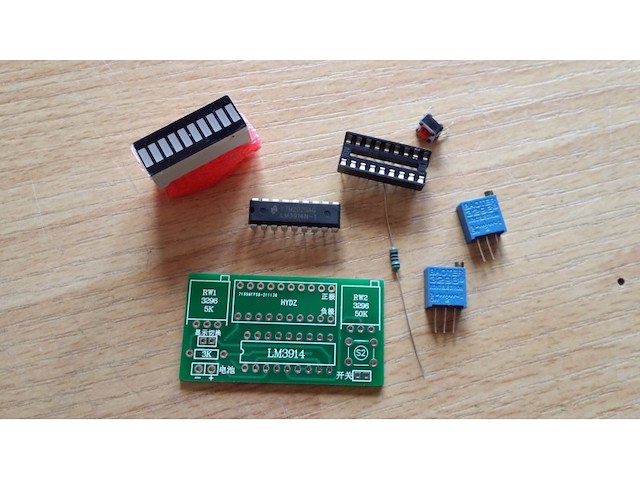
P13 LM3914 Diy Kits Display LED Indicator 10 Segment Capacity Power Level This is a DIY kits,need buyer to assemble it. Power display is to take some voltage, perform simulations show the percentage of segments, such as 3.7V lithium battery, take the lower voltage 3V, the upper limit of 4.2V, 4.2-3 = 1.2V, the voltage difference between the lower limit of 1.2V, is the battery Analog power up LM3914 can accurately detect an analog voltage, and 10 LED display, display dot mode LED is lit 10 one, or in a stripe pattern individually lit LED Display Description: Displays the battery voltage between the lower limit of 10 files showed that representatives of each of the lights 10% charge displays, on behalf of 10 lights display charge 0% -100% range; you can also change the single light display, is displayed only a light, more power, single-light power 4mA, all bright 42mA. Parameter: Power: bar display full brightness 42ma, single light shows 4ma Measuring range: the battery inside the common 2.4-20v Color: red, green, blue, send by random Display: Multi-light bar display or a single light dot display pcb board size: 49 x 25,9 mm Suitable for lithium batteries, lead-acid batteries and other power batteries need to be displayed Power adjustable display range for the battery discharge curve of a scientific setting, direct support: single lithium 1S (4.2V) ~ 4S (16.8V), lead acid 6V ~ 12V, NiMH 3.6V ~ 18V, nickel-cadmium batteries 3.6V ~ 18V A variety of high and low voltage battery display range adjustment: 1. Lithium battery: After the completion of a single lithium battery discharge voltage is 3V, when fully charged 4.2V; 1S correspond to 3V (first light) to 4.2V (tenth lights); 2S corresponds to 6V (first light) to 8.4V (tenth lights); 3S correspond to 9V (first light) to 12.6V (tenth lights); 4S correspond to 12V (first light) to 16.8V (tenth lights); Other series voltage and so on. 2. Lead Acid Batteries 6V or 12V lead-acid battery is generally: 6V corresponds to 4.8V (first red light) to 6.75V (tenth lights); 12V corresponds to 9.6V (first red light) to 13.5V (tenth lights); The module according to the above standard battery discharge range design, can accurately reflect the battery, so that users can readily observe the status of the battery. Adjustment of the following methods: Equipment needed: an adjustable power supply, precision accuracy of the decisions of the panel display. Watches word screwdriver. Case in single 3.7V lithium, 3V is less low-end power, 4.2V for the full power of high-end. 1, the adjustable power supply voltage to the desired voltage display high 4.2v, connect this board, this time there are two results: one is not bright, one is all bright or light a few. This time slow adjustment plate 503 (50k) potentiometer until the LED strip just lit up the whole. Several light does not shine or counterclockwise to adjust, when full light clockwise. 2, the adjustable power supply voltage to the low end of the desired 3V. Adjustment board 502 (5K) potentiometer to just light a LED, does not light clockwise adjustment, several or all bright light counterclockwise. 3, patiently repeating the first step two. Usually 2 times to adjust to the desired display range. Display Mode A / P: full brightness linear / single lamp lattice mode switch, the default is a linear model, the board set aside a switch pad, even with soldering pads can be turned into full light linear mode, no welding is the point like single light display Note: To adjust their voltage, according to the method of adjusting the order, to emphasize high-end, then adjust the low end.Red then positive, then negative black, must not be reversed, this module is the maximum limit voltage DC 20V, please use anti-static welding or soldering station pull electric heat welding. Package Contents 100% Brand New 1 x LM3914 10 Segment 5V 12V Battery Capacity Power Level LED
-
Mašine i alati chevron_right Ručni alat i rezervni delovi
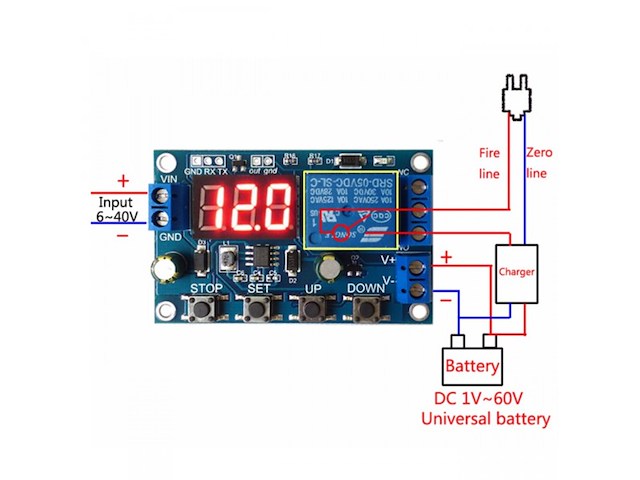
Modul koji moze mnogo toga da odradi kada je akumulator u pitanju. Moze da drzi ukljuceno ili iskljuceno rele u zadatim granicama, ukljuceno ili iskljuceno iznad/ispod zadatog napona, da se iskljuci kada se napuni akumulator itd... Ima mogucnost i serijske komunikacije. Kompletan opis rada je ispod na engleskom. Operating mode: Voltage upper limit: UL1, voltage lower limit nL1, the voltage upper limit is greater than the voltage lower limit (UL1> nL1) U-1: Charging measurement: When the measured voltage is lower than the lower limit voltage, the relay pulls above; the upper limit voltage, the relay is disconnected. U-2: charge measurement time control: set the charging time (OP); when the measured voltage is lower than the lower limit voltage, the relay pull, and then start the countdown OP time, the end of the timer, the relay off; when the measured voltage is higher than the upper limit voltage , The relay is disconnected. U-3: Discharge detection: When the measured voltage is lower than the lower limit voltage, the relay is off, above the upper limit voltage, the relay pulls; U-4: discharge detection time control: set the discharge time (OP); when the measured voltage is higher than the upper limit voltage, the relay pull, and then start the countdown OP time, the end of the timer, the relay off; when the measured voltage below the lower limit voltage , The relay is disconnected; U-5: voltage in the range, the relay pull: when the measured voltage between the upper and lower limits, the relay pull, the other circumstances open; U-6: voltage outside the interval, the relay pull: the measured voltage below the lower limit voltage or higher than the upper limit voltage, the relay pull, the other case the relay is off. Product parameters: 1: Power supply voltage: DC6--40V, voltage detection range DC 0--60V, suitable for less than 60V of the various batteries, voltage measurement error ± 0.1V. 2: charge and discharge time (OP) range: 0 - 999 minutes. How do I set parameters? First, according to their needs, to determine the requirements of the work model; According to the working mode of the relay, in the main interface (when the module is powered on, it will flash the current mode of operation, the default U-1 mode, and then enter the main interface) press the SET button for 2 seconds and then release, enter the selection Mode interface, UP, DOWN button to select the mode to be set (U-1 ~ U-6); After selecting the mode, assume that we have selected the U-1 mode and press the SET button to set the corresponding parameter. The parameter to be set will flash (UL1 voltage upper limit, nL1 voltage lower limit, OP conduction time), press UP, DOWN Key to increase or decrease, you can always press the key to quickly increase or decrease, press the SET button to set the current mode of the next parameter, the process above; Set the parameters, and then press the SET button for 2 seconds to release, the current setting mode will flash, and then return to the main interface, set the parameters of success! In the main interface, press the DOWN key to achieve voltage and time switching. Mode selection interface: press the SET button for a long time to enter the mode selection interface, set the finished, a long time press the SET button and then release the exit mode selection interface, back to the main interface. Additional features: Data upload: through the serial port to achieve data upload, interval 1s upload a voltage and run time, easy to post-data analysis; Serial port settings parameters: You can set the mode and parameters through the serial port, more convenient; An extra signal output, when the relay to meet the conditions, the output high, the other output low. Serial port control (TTL level communication) Communication standard: The baud rate is 115200 bps Data bits: 8 Stop bit: 1 Check digit: none Flow control: none Serial command: `U-1`: Operating mode (range U-1 to U-6) `000`: 0 - does not enable timing function, non-0 - enable timing function (range 001 to 999) `Dw02.9`: Set the lower limit voltage `Up10.1`: set the upper limit voltage (range 00.0V ~ 99.9V) `Get`: Get the current settings `On`: Allows the relay to turn on `Off`: Always turn off the relay `Start`: start uploading data `Stop`: stop uploading data The above command can be any combination of two, need to be separated by commas Such as: `dw02.9, up10.1` set the lower limit voltage 02.9V upper limit voltage 10.1V Upload Status: Test Voltage + On Time + Status `00.0V, 00: 00: 00, OP r n` 00.0V: Measured voltage 00:00:00: Relay on time Status: OP relay on, CL relay off STOP key function expansion: Relay enable mode: ON: OP conduction time, the relay allows conduction; OFF: The relay is disabled and is always off; Press the STOP button on the main interface to switch between ON and OFF, the current status will flash, and then return to the main interface. (This function is an emergency stop function, a key to disconnect the relay) Sleep mode: C-P sleep mode: within five minutes, without any operation, the digital tube automatically shut down the display, the program normal operation; O-d normal mode: digital tube is always open display; Press and hold the STOP button for 2 seconds to release, to achieve C-P and O-d state of the switch, the current state will flash, and then return to the main interface.
-
Mašine i alati chevron_right Ručni alat i rezervni delovi
P01 Battery charge and discharge module integrated voltmeter undervoltage and overvoltage protection timing charge and discharge with communication function Features: 1. Battery charge and discharge intelligent control 2. You can set the charge and discharge time 3. With serial communication function, real-time monitoring of the working status of the relay through the serial port 4. Additional signal output, when the relay to meet the conditions, the output high, you can control other equipment 5. A key emergency stop function (STOP button), with reverse protection, reverse does not burn Specifications: 1: Power supply voltage: DC 6--40V, voltage detection range DC 0--60V, suitable for less than 60V of the various batteries, voltage measurement error ± 0.1V 2: charge and discharge time (OP) range: 0 - 999 minutes Size: 5.9x3cm/2.32x1.18inch 1.Battery charge and discharge intelligent control; 2. You can set the charge and discharge time; 3. With serial communication function, real-time monitoring of the working status of the relay through the serial port; 4. Additional signal output, when the relay to meet the conditions, the output high, you can control other equipment. 5. A key emergency stop function (STOP button), with reverse protection, reverse does not burn. Operating mode: Voltage upper limit: UL1, voltage lower limit nL1, the voltage upper limit is greater than the voltage lower limit (UL1> nL1) U-1: Charging measurement: When the measured voltage is lower than the lower limit voltage, the relay pulls above; the upper limit voltage, the relay is disconnected. U-2: charge measurement time control: set the charging time (OP); when the measured voltage is lower than the lower limit voltage, the relay pull, and then start the countdown OP time, the end of the timer, the relay off; when the measured voltage is higher than the upper limit voltage , The relay is disconnected. U-3: Discharge detection: When the measured voltage is lower than the lower limit voltage, the relay is off, above the upper limit voltage, the relay pulls; U-4: discharge detection time control: set the discharge time (OP); when the measured voltage is higher than the upper limit voltage, the relay pull, and then start the countdown OP time, the end of the timer, the relay off; when the measured voltage below the lower limit voltage , The relay is disconnected; U-5: voltage in the range, the relay pull: when the measured voltage between the upper and lower limits, the relay pull, the other circumstances open; U-6: voltage outside the interval, the relay pull: the measured voltage below the lower limit voltage or higher than the upper limit voltage, the relay pull, the other case the relay is off. Product parameters: 1: Power supply voltage: DC6--40V, voltage detection range DC 0--60V, suitable for less than 60V of the various batteries, voltage measurement error ± 0.1V. 2: charge and discharge time (OP) range: 0 - 999 minutes. How do I set parameters? 1. First, according to their needs, to determine the requirements of the work model; 2. According to the working mode of the relay, in the main interface (when the module is powered on, it will flash the current mode of operation, the default U-1 mode, and then enter the main interface) press the SET button for 2 seconds and then release, enter the selection Mode interface, UP, DOWN button to select the mode to be set (U-1 ~ U-6); 3. After selecting the mode, assume that we have selected the U-1 mode and press the SET button to set the corresponding parameter. The parameter to be set will flash (UL1 voltage upper limit, nL1 voltage lower limit, OP conduction time), press UP, DOWN Key to increase or decrease, you can always press the key to quickly increase or decrease, press the SET button to set the current mode of the next parameter, the process above; 4. Set the parameters, and then press the SET button for 2 seconds to release, the current setting mode will flash, and then return to the main interface, set the parameters of success! 5. In the main interface, press the DOWN key to achieve voltage and time switching. Mode selection interface: press the SET button for a long time to enter the mode selection interface, set the finished, a long time press the SET button and then release the exit mode selection interface, back to the main interface. Additional features: 1. Data upload: through the serial port to achieve data upload, interval 1s upload a voltage and run time, easy to post-data analysis; 2. Serial port settings parameters: You can set the mode and parameters through the serial port, more convenient; 3. An extra signal output, when the relay to meet the conditions, the output high, the other output low. Serial port control (TTL level communication) Communication standard: The baud rate is 115200 bps Data bits: 8 Stop bit: 1 Check digit: none Flow control: none Serial command: `U-1`: Operating mode (range U-1 to U-6) `000`: 0 - does not enable timing function, non-0 - enable timing function (range 001 to 999) `Dw02.9`: Set the lower limit voltage `Up10.1`: set the upper limit voltage (range 00.0V ~ 99.9V) `Get`: Get the current settings `On`: Allows the relay to turn on `Off`: Always turn off the relay `Start`: start uploading data `Stop`: stop uploading data The above command can be any combination of two, need to be separated by commas Such as: `dw02.9, up10.1` set the lower limit voltage 02.9V upper limit voltage 10.1V Upload Status: Test Voltage On Time Status `00.0V, 00:00: 00, ON \ r \ n` 00.0V: Measured voltage 00:00:00: Relay on time Status: OP relay on, CL relay off STOP key function expansion: Relay enable mode: 1. ON: OP conduction time, the relay allows conduction; 2. OFF: The relay is disabled and is always off; Press the STOP button on the main interface to switch between ON and OFF, the current status will flash, and then return to the main interface. (This function is an emergency stop function, a key to disconnect the relay) Sleep mode: 1. C-P sleep mode: within five minutes, without any operation, the digital tube automatically shut down the display, the program normal operation; 2. O-d normal mode: digital tube is always open display; Press and hold the STOP button for 2 seconds to release, to achieve C-P and O-d state of the switch, the current state will flash, and then return to the main interface.
-
Mašine i alati chevron_right Ručni alat i rezervni delovi
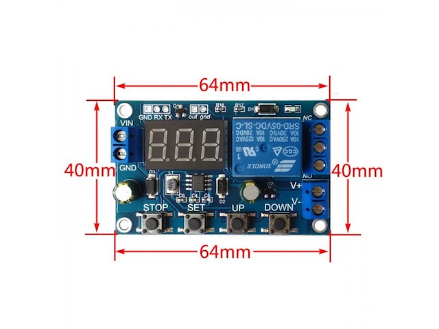
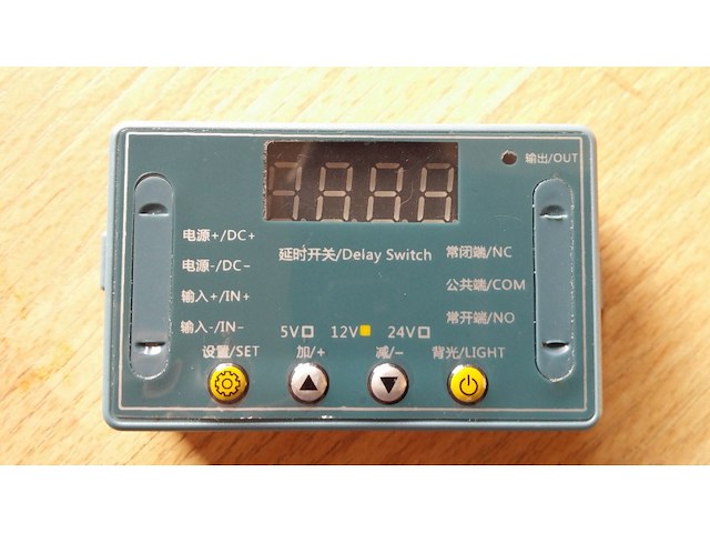
K15 Multi-mode delay time relay module 32 modes of pulse delay time delay time delay high precision programmable optocoupler isolation 5 v12v24v optional The multi-function relay control module is specially designed for users with various requirements. It adopts the microcontroller as the main control unit with 32 functions preset. Users can use the corresponding specific functions according to the actual requirements. Can be used in water pump control, motor control, lamp belt control, solenoid valve control and so on. 1. New upgrade, increasing the number of module functions to 32, to meet more application requirements. 2. Anti-backconnection function of power supply, which will not damage the module due to wrong power supply. 3. Timing accuracy to 0.01 second. 0.1 seconds (minimum) ~999 minutes (maximum) optional 4.. Low power saving Settings, you can turn off the display area. Product parameters: Commodity name: Multi-function delay relay Relay V number: DC5V/12V/24V optional Input voltage: 5V Version: DC5V power supply; 12V version: DC12V power supply; 24V version: DC24V power supply Output load: dc 30V, Max 10A. Ac 250V, maximum 5A. Trigger signal: 5V version (high level: 5V); Both 12V (HIGH level: 12V) and 24V (high level: 5V) low levels are 0V. Static current: 20mA Operating current: 60mA Operating temperature: -25℃-85℃ Power off memory: Yes Product weight: ≈26g, product size: 65 x 34.3 X 17.5 (MM) Manual measurement is for reference only. The actual size is subject to the material object Warm tips: 1. Please select the required V version (according to the relay identification difference above, the relay is 5V instant 5V version) to avoid wrong purchase. 2. The output of relay is passive contact without current output to control the on-off effect of a line. 3. Please input the trigger voltage strictly according to the selected version Instructions for use: Working mode (32 kinds) : P-11: Inching mode with suction and no disconnection. P-12: Self-locking mode, and the relay state is reversed once after each trigger. P-13: When triggered, the relay pulls in and disconnects after A time delay; Invalid trigger during delay. P-14: When triggered, the relay pulls in and disconnects after A time delay; Retiming is triggered during a delay. P-15: When triggered, the relay pulls in and disconnects after A time delay; Accumulative timing is triggered during delay. P-16: When triggered, the relay pulls in and disconnects after A time delay; Trigger reset (relay disconnection) during delay. P-17: When triggered, the relay pulls in during the signal duration, the input signal disappears, and the relay is disconnected after A time delay; During the delay, the relay is triggered again to keep the suction, and the timing stops until the last signal disappears, and the relay is disconnected after the delay of time A. P-18: After the power is switched on, the relay will pull in immediately and disconnect after A second delay; Until the next power cut. P-21: Signal feed, relay suction after delay A time. P-22: Give the continuous signal. After A time, the relay pulls in; The signal disappears and the relay disconnects. P-23: When the signal disappears beyond time A, the relay pulls in; There is a signal, the relay is off. P-24: Give the continuous signal. After A time, the relay pulls in; When the signal disappears beyond time A, the relay is disconnected. P-25: Give the continuous signal. After A time, the relay pulls in; Give the continuous signal again, after A time, the relay is disconnected P-26: Signal is given and the relay is disconnected after absorbing A time; After the signal disappears, the relay pulls in again for A second and then stops P-27: the relay with pulse signal (rising edge or falling edge) is disconnected, and there is no pulse signal. The relay will be absorbed after A time delay (both continuous high level and continuous low level are considered to have no pulse). P-28: After power on, the relay will pull in after delay time A until power off. P-31: After power on, the relay pulls in time A and disconnects time B, infinite cycle; The power is off. P-32: With continuous signal, the relay pulls in A time, disconnects B time, infinite cycle; The signal disappears and the loop is terminated. P-33: Give A signal, the relay pulls in A time, disconnects B time, infinite cycle; Give the signal one more time to stop the loop. P-34: After power on, the relay will pull in after delay time A, and disconnect after pull in time B. P-35: Signal is given once. After delay of time A, the relay pulls in and shuts off after time B. P-36: Give the continuous signal. After A time, the relay will pull in and disconnect after B time. Signal disappeared, time reset, relay disconnected. P-37: There is A signal. The relay will automatically disconnect after it pulls in time A, and then timing time B after it is disconnected. The signal trigger will be invalid within time A+B. P-38: There is A signal. The relay will automatically disconnect after absorbing A time, and then timing B time after disconnecting, and automatically disconnect after absorbing A time again. P-41: No action on signal; Signal vanishing trigger; The relay is disconnected after absorbing the delay time of A. P-42: the signal disappears and the relay pulls in after A time delay; The relay disconnects after B time delay. P-43: The signal disappears, and the relay pulls in after the disappearance exceeds time A; The relay disconnects after B time delay. P-44: After power on, the relay attracts time A and disconnects time B; The relay disconnects and stops after C cycles. P-45: No action after power on; After giving the signal, the relay attracts A time and disconnects B time; The relay disconnects and stops after C cycles. Give the signal, then execute again. P-46: When the signal is given more than A times, the relay pulls in; Keep the suction; The power is off. P-47: When the signal is given more than A times, the relay pulls in; Disconnect after suction B time. P-48: In C time, after continuous signal feeding for more than A times, the relay will disconnect and stop after absorbing B time. Table showing the position of the decimal point and the unit of time it represents: The decimal point is in the hundreds place, and the time range is 0.01~9.99 seconds Xx. X decimal point in ten place, time range 0.1~99.9 seconds XXX has no decimal point and the time range is 1-999 seconds XXX. The decimal point is in one place and the time range is 1-999 minutes Turn off display: In non-set state, press K4 to turn off the display screen, then press again to open it again. Description of working parameters setting: Hold down the K1 key and hold it until p-XX appears on the screen 2 seconds later. Press K2 and K3 to change the working mode. After selecting the working mode, press K1 to enter the time setting of A, and Axxx is displayed on the screen. At this time, press K2 and K3 to modify the time parameters of A, press K2 and K3 to add and subtract 1 for short, long to add and subtract 10 for fast, and press K4 to set the position of the decimal point. After setting time A, press K1 to set time B. BXXX is displayed on the screen. At this time, press K2 and K3 to modify time parameters of B; press K2 and K3 to add or subtract 1 for short; press K4 to add or subtract 10 for long; and press K4 to set the position of the decimal point. After setting the B time (in the case that the mode has C cycle number parameter), press K1 to set the C cycle number, and the screen shows Cxxx. At this time, press K2 and K3 to modify the C cycle number parameter, press K2 and K3 to add or subtract 1 for short, and press long to add or subtract 10 for fast. After setting, press the K1 key one last time to exit the setting state and save all parameters. Description of wiring port: DC+ input DC power positive pole DC- input DC power negative pole IN+ signal input positive pole IN- negative input terminal NO relay always start interface, relay suction and COM short connected, not closed suspension; COM relay common end interface Normally closed end interface of NC relay. When the relay fails to suck, it is short connected with COM. When the pull, it is suspended.
Istorija cene
Naziv oglasa
Početna cena
Najveća cena
Najniža cena
Nema podataka o istoriji cene

Pretraga: " "
Uspešno ste zapratili pretragu.
Sve zapraćene pretrage možete videti u
korisničkom panelu.