

Pratite promene cene putem maila
- Da bi dobijali obaveštenja o promeni cene potrebno je da kliknete Prati oglas dugme koje se nalazi na dnu svakog oglasa i unesete Vašu mail adresu.
1-25 od 644 rezultata
Prati pretragu "slicni:108087349 Donna Summer-On the radio -(kaseta)"
Vi se opustite, Gogi će Vas obavestiti kad pronađe nove oglase za tražene ključne reči.
Gogi će vas obavestiti kada pronađe nove oglase.
Režim promene aktivan!
Upravo ste u režimu promene sačuvane pretrage za frazu .
Možete da promenite frazu ili filtere i sačuvate trenutno stanje

-
Mašine i alati chevron_right Ručni alat i rezervni delovi
Prodajem radio stanicu Motorola GM300 sa dve antene i drzacem za kola. 063 566 674
-
Mašine i alati chevron_right Ručni alat i rezervni delovi
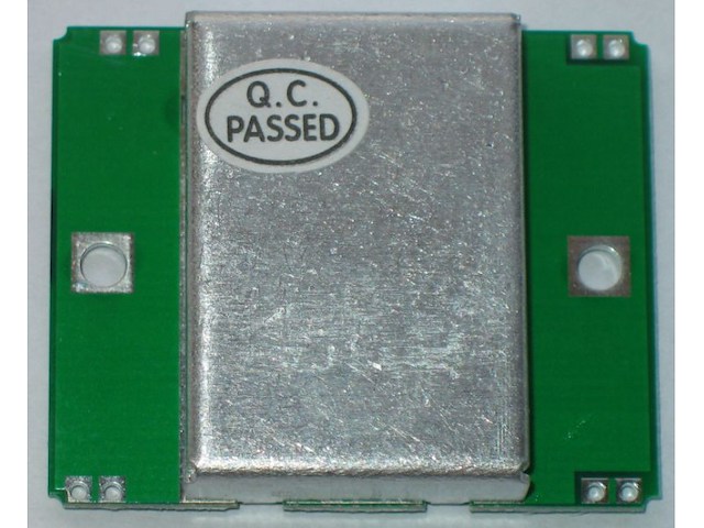
Mikrotalasni senzor pokreta koji radi po dopler principu idealan za sredine sa smetnjama posto je otporan na uticaj svetlosti, radio smetnji, prasine, magle... U pitanju je samo senzor zgodan za razne eksperimente i potrebno je napraviti dodatnu elektroniku da bi bio u funkciji. Na jednoj slici se vidi primer a na googlu se pronadje jos dosta nacina upotrebe, potrebno je traziti `HB100 microwave`. Product Description HB100 microwave module is using Doppler Radar (Doppler Radar, the principle of design of microwave detector, moving object is mainly used in automatic door control switch, safety guard system, ATM ATM automatic video control system, automatic train signal etc.HB100 is a standard 10.525 GHz microwave doppler radar, this way of detecting compared with other detection method has the following advantages: 1, non-contact detection;2, is not affected by temperature, humidity, noise, air, dust, light effects, such as suitable for bad environment;3, radio frequency interference resistance ability;4, the output power is small, no harm to human body;5, detection range of distance: more than 20 meters. Doppler principle introduction: doppler theory is based on time, when the radio waves objects encountered in the process of marching the waves will be reflected, and the frequency of the reflected wave will change with met the moving state of the object.If radio waves hit the position of the object is fixed, so the frequency of the reflected wave and transmitted wave frequency should be equal.If the object moving in the direction of the launch, the reflected wave will be compressed, means that the frequency of the reflected wave increase;Whereas the frequency of the reflected wave will be less. Designed according to the principle of doppler microwave detector by the medium droz microwave FET oscillation source (10.525 GHz), power divider, transmitting antenna and receiving antenna, mixer, detector circuit component (figure 2).Transmitting antenna beam transmission microwave outward, when an object is reflected, the reflected wave is receiving antenna, then to the mixer and oscillation wave mixing, mixing, after the detection of low frequency signal reflect the speed of moving objects A long, size: 37 mm X 45 mm wide X 8 mm high Second, the main chip: HB100 microwave sensor Three, working voltage: DC 5 V + / - 0.25 V Four, features: Launch: 1 transmitting frequency: 10.525 GHz 2: frequency setting precision 3 MHZ 3 power output (minimum) : 13 DBM EIRP 4: working voltage 5 V + / - 0.25 V 5 working current (the CW) : 60 ma Max., 37 ma typical Harmonic emission: < - 10 DBM 7 pulse work mode: 5% 8 average current (DC) : 2 ma typ. 9 pulse width (Min.) : 5 usec 10 load cycle (Min.) : 1% Reception: 1 sensitivity (10 db S/N thewire) 3 hz - 80 hz bandwidth: - 86 DBM 3 hz - 80 hz bandwidth clutter 10 uv 2 antenna gain: 8 class: : dbi 3 vertical plane 3 db beam width: 36 degrees Level 3 db beam width: 72 degrees Weight: 8 g
-
Mašine i alati chevron_right Ručni alat i rezervni delovi
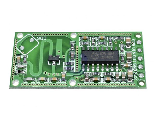
Mikrotalasni senzor pokreta koji radi po dopler principu idealan za sredine sa smetnjama posto je otporan na uticaj svetlosti, radio smetnji, prasine, magle. . . Napon napajanja je 4-28V a izlaz je 3.3V. Moze da detektuje pokret iza prepreka, stakla pa i tanjih zidova. Feature: Transmission signal processing control chip RCWL-9196 Wide operating voltage range: 4.0-28.0V Compared with the traditional infrared feeling PIR, with the penetrating detection capability Block time, distance adjustable Iutput 3.3V power supply Application: The sensing face in front of the gold without any shelter. Front and rear sensing surface space to set aside more than 1CM The module carrier plane and install as flat line A certain application of effective detection area The component side of the module is positive sensing face, the opposite is negative sensing surface. Negative sensing surface sensing less effective Microwave modules can not be large-scale applications in the same area, otherwise there will be mutual interference. Between single individuals over distance greater than 1M

-
Mašine i alati chevron_right Ručni alat i rezervni delovi
Digitalni termostat , termoregulator u kucistu. Opseg regulisanja temperature: -19 do 99C Greska merenja: 0.3C Rezolucija: 0.1C Senzor Model: NTC (10K/B3435) Tacnost regulacije: 1C Napon napajanja: AC 220V Struja kontakta relea: 10A. Radna temperatura: 0~50 Dimenzije: 81x55x31mm Moze da radi u rezimu hladjenja i grejanja, na levom displeju se zada jedna temperatura, na desnom druga a centralni prilazuje trenutnu. Usage method: 1. Plug the plug of this product to a household socket. If the screen displays temperature, it means the power supply has been correctly connected. 2. Put the temperature control probe into the places that need temperature control, and set the start and stop temperature according to your needs. 3. Plug the plugs of heating and refrigeration devices to the socket of temperature controller, and then you can achieve temperature control. Operation instructions: After power-on, if the temperature is within the range, you should immediately start the output and make it stop when it reaches the set value. Start temperature For example, if you want to control water boiling to stop at 60 Celsius degrees and start over at 45 Celsius degrees, then you should set the start value as 45 and stop value as 60. Start temperature > stop temperature: refrigeration mode For example, in summer, you want to control the greenhouse to start the scavenger fan when the temperature is higher than 35 Celsius degrees and stop at 32 Celsius degrees, then you should set the start value as 35 and stop value as 32. SET: function button/power-on & power-off button In the state of power-on, you can switch off by a long press for 3 seconds. After switched off, it will still remain power-off if there is no power supply. In the state of power-off, you can switch on by pressing SET once. After switched on, it will still remain power-on if there is no power supply. In the state of normal temperature control, you can switch between F-1~F-3 by pressing SET once. F-1 intermittent work mode unit: minute left: start minute right: stop minute F-2 time switch left: hour right: minute 99h59mins max F-3 time switch left: hour right: minute 99h59mins max Temperature correction: Enter the temperature correction function by removing the controller plug and pressing SET to supply power. The screen displays –00--. You can increase or decrease temperature on the basis of the original temperature, maximum range -9.9~+99. After correction: Real-time temperature = the temperature before correction + the corrected value Press (start+-) power-on to enter self-check function; Press (stop+-) power-on to restore factory settings. Restore factory settings: If there is some setting mistake or setting disorder, you can press the two stop buttons to restore factory settings. When the screen displays 88-888-88, and the buzz gives out a long sound, it means the restoration has finished.
-
Mašine i alati chevron_right Ručni alat i rezervni delovi
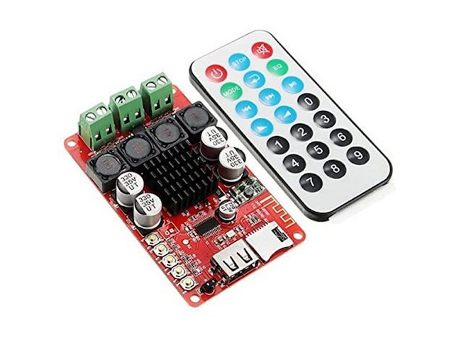
Pojacalo 2x50W sa daljinskim. Moze da se komanduje putem daljinskog kao i tastera na modulu. Features: TPA3116 power amplifier chip, 2x50W stereo power output. bluetooth 4.0, a perfect bluetooth audio receiver board for use. USB interface/TF card slot, supported playing formats: MP3, WMA, WAV, FLAC. With FM radio function. DC 8-26V input voltage for power supply. The wireless receive distance can be up to 15m(shielded signals). Equipped with heat-dissipating module on the board. With 5 buttons on the board for adjustment, convenient and easy operation. Remote control for receiving and controlling(infrared way). Specifications: Audio Input: bluetooth V4.0, USB decoding, TF card decoding Decoding Supported Formats: MP3, WMA, WAV, FLAC Power Supply: DC 8-26V Applicable Impedance: 4-8 ohm Control Method: Remote Control Receive Distance: 15 meters Remote Control Power: 1 * 3V CR2025 Button Battery(Included) PCB Board Size: 84.9 x 51.7mm Package Weight: 67g
-
Mašine i alati chevron_right Ručni alat i rezervni delovi
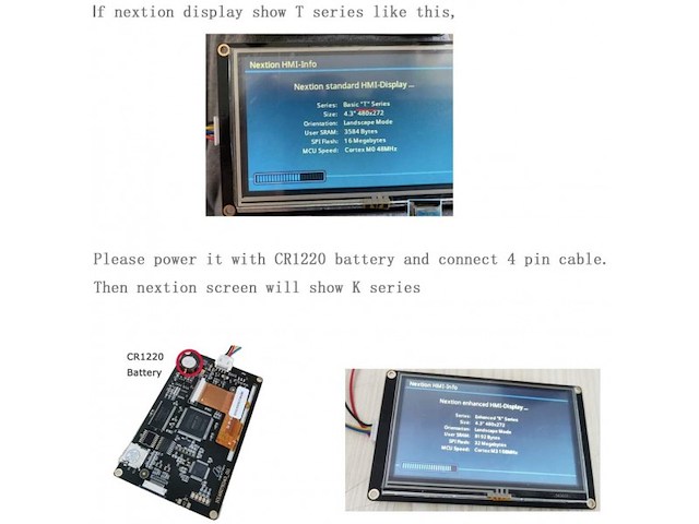
Nextion 2.8` displej sa touch-om. Potrebno mu je solidno napajanje da bi radio kako treba a komunikacija se obavlja serijski (primer na zadnjoj slici), Naprednija verzija koja ima GPIO port, EEprom. . . Nextion Enhanced NX3224K028 is a powerful 2.8” HMI TFT display, with 16MB Flash data storage space, 1024 bytes EEPROM, 3584 bytes RAM. With GPIO supported, now customers can use Nextion to control external devices. Nextion is a seamless Human Machine Interface (HMI) solution that provides a control and visualization interface between a human and a process, machine, application or appliance. Nextion is mainly applied to the Internet of thing (IoT) or the consumer electronics field. It is the best solution to replace the traditional LCD and LED Nixie tube. Nextion includes a hardware part (a series of TFT boards) and a software part (the Nextion editor). The Nextion TFT board uses only one serial port to communicate. It lets users avoid the hassle of wiring. We noticed that most engineers spend much time in application development but get unsatisfactory results. As a solution to this situation, Nextion editor has mass components such as button, text, progress bar, slider, instrument panel etc. to enrich the interface design. Furthermore, the drag-and-drop function ensures that users spend less time in programming, which will reduce 99% of their development workloads. With the help of this WYSIWYG editor, designing a GUI is a piece of cake. It’s easy to adapt Nextion family HMI to existing projects- users just need to provide it a UART. Features: Supports built-in RTC Supports GPIO SD Card interface: support max 32G Micro TF/SD card (FAT32 file format) Instruction buffer: 1024 bytes Color: 65K (65536) colors Resolution: 320×240 pixel Adjustable Brightness:0~180 nit- the interval of adjustment is 1% Certificates: CE/EMC, RoHS (certificates) Package Includes: 1 x Nextion Enhanced NX3224K028 – Generic 2.8” HMI Touch Display 1× Power supply test board 1× 4-pin grove cable
-
Mašine i alati chevron_right Ručni alat i rezervni delovi
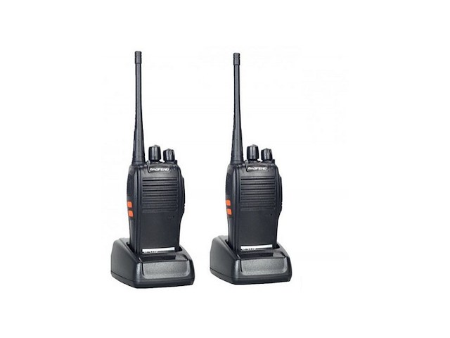
`- Karakteristike: Talk Range 3-5km Type: Two Way Radio Dimensions 60X33X115mm(Not Antenna) Frequency Range 400 ~ 470MHz - U kompletu dobijate: 2 x stanice BF-777S 2 x baterije 2 x antene 2 x punjača 2 x štipaljke za kaiš 2 x upustvo

-
Mašine i alati chevron_right Ručni alat i rezervni delovi
`- Karakteristike: Talk Range 3-5km Type: Two Way Radio Dimensions 60X33X115mm(Not Antenna) Frequency Range 400 ~ 470MHz - U kompletu dobijate: 2 x stanice BF-777S 2 x baterije 2 x antene 2 x punjača 2 x štipaljke za kaiš 2 x upustvo
-
Mašine i alati chevron_right Ručni alat i rezervni delovi
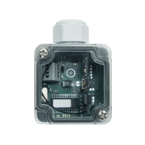
Opis KONVERZIJA SIGNAL SA SENZORA (HF TRANSMITERA) U RS485 SIGNAL
-
Mašine i alati chevron_right Ručni alat i rezervni delovi
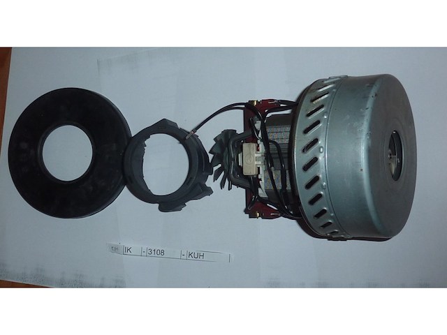
Zepter Cleansy, elektromotor. Usisivač je radio, ali navodno nekad nije hteo da se upali neposredno nakon gašenja, a kad prođe vreme upali se. IK - 3108 - KUH
-
Mašine i alati chevron_right Ručni alat i rezervni delovi
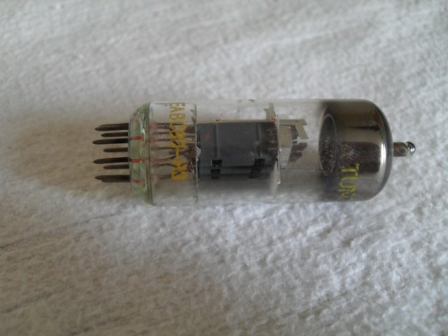
LAMPA EABC 80-H3 - RADIO LAMPA EABC 80-H3 Proizvodjac lampe je Tungsram. Lampa je kupljena u prodavnici u inostranstvu pre mnogo mnogo godina. Nikada nije upotrebljena. Slikao sam `noge` pa mozete pogledati kako izgledaju. Na fotografijama mozete pogledati detalje. Ako Vam nesto nije jasno ili smatrate da nisam napisao pitajte i ja cu Vam odgovoriti. SLANJE-ISPORUKA-DOSTAVA -Saljemo navedenom kurirskom sluzbom i postom (kao vrednosno pismo sa otkupninom). -Placanje kupljenog predmeta je moguce samo na navedene nacine. -Postanske troskove placa kupac prema tarifi odabrane poste. -Licno preuzimanje je iskljucivo na mojoj adresi. -Ostale varijante slanja i placanja mi za sada ne odgovaraju.
-
Mašine i alati chevron_right Ručni alat i rezervni delovi
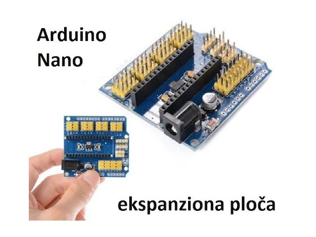
Arduino Nano ekspanziona ploča V3 - Expansion Shield Sa ovim shield-om praktično radite lako proširenje Arduina Nano za lako povezivanje drugih periferija kao što su servo motori, senzori i druge periferije. Takođe spoljašnji konektori su u standardnom rasporedu za Arduino Uno što Vam omogućava da sa Nanom koristite standardne shieldove za razvoj i prototipove (kao što su keypad shield, lcd tft shield, ethernet shield i mnogi drugi. . .) Karakteristike: - 14 ulazno-izlaznih pinova (servo tip sa GND, napajanje i signali,...) - 8 analognih pinova sa izlaznim naponom i masom - 6 PWM pinova - 1 servo power izlaz - I2C expansion pin - AREF izlaz - 3.3V izlaz - Dimenzije: 56 x 53 mm (approx) Ovo je orginalna specifikacija proizvodjaca: Draw out all of the digital I/o mouth and analog I/o mouth, every IO mouth has the positive and negative power supply interface standard Lead the I2C interface on the main board, convenient and connection of the I2C device Increase the DC power supply interface. The NANO plate on the USB interface power supply current is actual only 50 ma, to bring high current equipment such as steering gear, when I was at this time in DC power supply interface provides an external power supply, ensure the stability of equipment operation. 14 I/O Pin (servo type with GND, power and signal) 8 analog Pin with power output and GND 6 PWM Pin 1 Servo power input I2C expansion Pin AREF output 3.3V output
-
Mašine i alati chevron_right Ručni alat i rezervni delovi
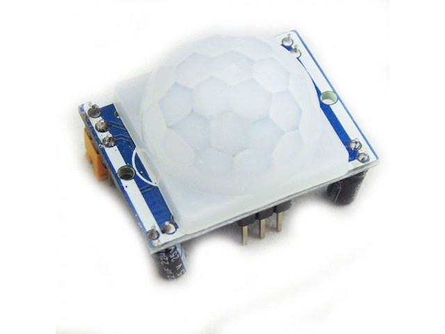
P09 1, the automatic sensor: to enter the sensor output range is high, people leave the sensor range of the automatic delay off high, output low. 2,the photosensitive control (optional, factory is not set) may set the photosensitive control during the day or light intensity without induction. 3, the temperature compensation (optional, factory is not set): In the summer when the ambient temperature rises to 30 ~ 32 ?, slightly shorter detection range, temperature compensation can be used as a performance compensation. 4, two trigger mode: (can be selected by jumpers) a, cannot repeat the trigger: the sensor output high, the delay time is over, the output will automatically become low from high; b, repeatable trigger: the sensor output high after the delay period, if the human body in its sensing range activities, its output will remain high until after the delay will be left high to low (sensor module review Measured activities of each body will be automatically extended after a delay time, and the final event of the delay time Starting point of time). 5, with induction blocking time (the default setting: 2.5S block time): sensor module, after each sensor output (high change Into a low level),you can set up a blockade followed by time period, in this time period the sensor does not accept any sensor signal. This feature can have a `sensor output time` and `blocking time` the interval between the work produced can be applied to detect the interval Products; also inhibit this function during load switching for a variety of interference. (This time can be set at zero seconds - Tens of seconds). 6, the working voltage range: the default voltage DC4.5V-20V. 7, micro-power consumption: static current `50 microamps, especially for battery-powered automatic control products. 8, the output high level signals: types of circuits can be easily and docking. Features Product Type: HC--SR501 Body Sensor Module Operating voltage range: DC 4.5-20V Quiescent Current: <50uA Level output: High 3.3 V /Low 0V Trigger: L cannot be repeated trigger/H can be repeated trigger(Default repeated trigger) Delay time: 5-200S(adjustable) the range is (0.xx second to tens of second) Block time: 2.5S(default)Can be made a range(0.xx to tens of seconds Board Dimensions: 32mm*24mm Angle Sensor: <100 ° cone angle Operation Temp: -15-+70 degrees Lens size sensor: Diameter:23mm(Default) Instructions: 1. Sensing module for about a minute after power initialization time, during the interval to the output module 0-3 times a minute in standby mode. 2. Should avoid direct lighting such as interference sources close the surface of the lens module so as to avoid the introduction of interference signal generator malfunction; use of the environment to avoid the flow of the wind, the wind sensor will also cause interference. 3. Sensor module using a dual probe, the probe`s window is rectangular, dual (A per B million) in the direction of the ends of long, when the body passed from left to right or right to left when the reach the dual IR time, distance difference, the greater the difference, more sensitive sensors, when the body from the front to the probe or from top to bottom or from bottom to top direction passing, dual IR not detected changes in the distance, no difference value, the sensor insensitive or does not work; so the sensors should be installed dual direction of the probe with human activities as much as possible parallel to the direction of maximum to ensure that the body has been passed by the dual sensor probe. To increase the sensing range of angles, the module using a circular lens, the probe also makes sense on all four sides, but still higher than the upper and lower left and right direction of sensing range, sensitivity and strong, still as far as possible by the above installation requirements.VCC, trig (control side), echo (receiving end), GND 4. Dimensions and Adjustment: Note: The potentiometer clockwise to adjust the distance, sensing range increases (about 7 meters), on the contrary, sensing range decreases (about 3 meters).Delay adjustment potentiometer clockwise rotation, sensor delay longer (about 300S), the other hand, induction by the short delay (about 5S). 5. Applications a, Security Products b, the human body sensors toys c, the human body sensor lighting d, industrial automation and control, etc. It can automatically and quickly open various types of incandescent, fluorescent lamps, buzzer, automatic doors, electric fans, automatic washing machine and dryer Machines and other devices, is a high-tech products. Especially suitable for enterprises, hotels, shopping malls, warehouses and family aisles, corridors and other sensitive Sense of region, or for the security zone automatic lighting, lighting and alarm systems. Package Include: 1* HC-SR501 Human Sensor Module

-
Mašine i alati chevron_right Ručni alat i rezervni delovi
Lot sa slika. Vakum lampe u kutijama su odgovarajuce i neupotrebljavane a i dosta lampi bez kutija su neupotrbljene. Pojacalo `lampas` i pojacalo `snagas` nisu predmeti ove prodaje, prodaju se posebno dakle u lot za prodaju ulaze samo 4 zvucnika ( slika br. 4 ).
-
Mašine i alati chevron_right Ručni alat i rezervni delovi
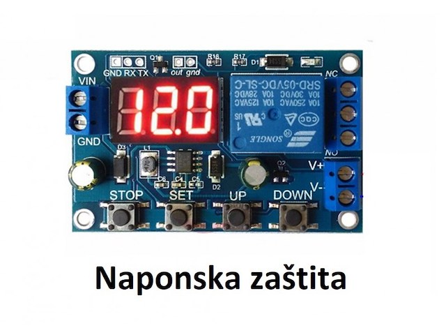
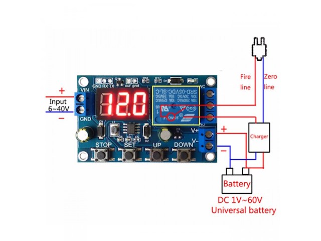
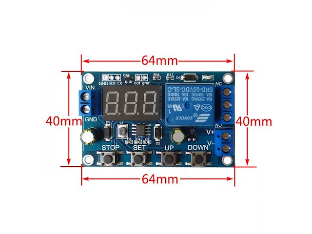
Prenaponska i podnaponska zaštita podesiva 0-40V DC Modul detektuje napon i prikazuje ga na displeju. Ukoliko je napon viši ili niži od zadatog isključuje izlazni rele i uključuje žvučnu signalizaciju (alarm) koji može da se isključi džamperom na ploci i LED indikaciju plave boje. Karakteristike: - Napon napajanja: DC 6-40 V - Napon detekcije i kontrole: 0-60 V DC - Izlazni rele: 30VDC/220VAC - 10A - Rele: NO + NC kontakt (normalno otvoren + normalno zatvoren) - Statička struja: 20 mA - Potrošnja u radu: 50 mA - Dimenzije: 60 x 40 x 18 mm Voltage upper limit: UL1, voltage lower limit nL1, voltage upper limit greater than Voltage lower limit (UL1>nL1) U-1: Charging measurement: when the measured voltage is lower than the lower limit voltage, the relay will be pulled up; if the voltage is upper limit, the relay will be disconnected. U-2: Charge measurement time control: set the charge time (OP); when the measured voltage is lower than the lower limit voltage, the relay is closed, and then starts to count down the OP time, ends the timer, and the relay turns off; when the measured voltage is higher than the upper limit voltage , the relay is turned off. U-3: Discharge detection: when the measured voltage is lower than the lower limit voltage, the relay is disconnected, and when the upper limit voltage is exceeded, the relay is pulled; U-4: Discharge detection time control: set the discharge time (OP); when the measured voltage is higher than the upper limit voltage, the relay is closed, and then starts to count down the OP time, the timer ends, and the relay is disconnected; when the measured voltage is lower than the lower limit voltage When the relay is disconnected; U-5: Within the voltage range, the relay pulling force: when the measured voltage is between the upper and lower limits, the relay is pulled, and other conditions are open; U-6: The voltage exceeds the interval, relaypull: The measured voltage is lower than the lower limit voltage or higher than the upper limit voltage, the relay is pulled, and the relay is closed in other cases. Voltage detection range DC0--60V, suitable for various batteries below 60V, voltage measurement error ±0.1V. 2: Charge and discharge time (OP) range: 0-999 minutes. How to set parameters? 1. First, determine the requirements of the working model according to your own needs; 2. According to the working mode of the relay, in the main interface (when the module is powered on, the current operation mode will flash, the default U-1 mode, and then enter the main interface) press the SET button for 2 seconds and release it to enter the selection mode interface, UP, DOWN button to select the mode to be set (U-1~U-6); 3. After selecting the mode, suppose we have selected the U-1 mode and pressed the SET button to set the corresponding parameters. The parameter to be set will flash (UL1 voltage upper limit, nL1 voltage lower limit, OP conduction time), press the UP, DOWN keys to increase or decrease, you can press the key to increase or decrease quickly at any time, press the SET button to set the next parameter The current mode, the above process; 4. Set the parameters, then press and hold the SET button for 2 seconds to release, the current setting mode will flash, and then return to the main interface, the parameters are set successfully! 5. On the main interface, press the DOWN key to switch between voltage and time. Mode selection interface: long press the SET key to enter the mode selection interface, after setting, long press the SET key, then release to exit the mode selection interface and return to the main interface.
-
Mašine i alati chevron_right Ručni alat i rezervni delovi
P01 Battery charge and discharge module integrated voltmeter undervoltage and overvoltage protection timing charge and discharge with communication function Features: 1. Battery charge and discharge intelligent control 2. You can set the charge and discharge time 3. With serial communication function, real-time monitoring of the working status of the relay through the serial port 4. Additional signal output, when the relay to meet the conditions, the output high, you can control other equipment 5. A key emergency stop function (STOP button), with reverse protection, reverse does not burn Specifications: 1: Power supply voltage: DC 6--40V, voltage detection range DC 0--60V, suitable for less than 60V of the various batteries, voltage measurement error ± 0.1V 2: charge and discharge time (OP) range: 0 - 999 minutes Size: 5.9x3cm/2.32x1.18inch 1.Battery charge and discharge intelligent control; 2. You can set the charge and discharge time; 3. With serial communication function, real-time monitoring of the working status of the relay through the serial port; 4. Additional signal output, when the relay to meet the conditions, the output high, you can control other equipment. 5. A key emergency stop function (STOP button), with reverse protection, reverse does not burn. Operating mode: Voltage upper limit: UL1, voltage lower limit nL1, the voltage upper limit is greater than the voltage lower limit (UL1> nL1) U-1: Charging measurement: When the measured voltage is lower than the lower limit voltage, the relay pulls above; the upper limit voltage, the relay is disconnected. U-2: charge measurement time control: set the charging time (OP); when the measured voltage is lower than the lower limit voltage, the relay pull, and then start the countdown OP time, the end of the timer, the relay off; when the measured voltage is higher than the upper limit voltage , The relay is disconnected. U-3: Discharge detection: When the measured voltage is lower than the lower limit voltage, the relay is off, above the upper limit voltage, the relay pulls; U-4: discharge detection time control: set the discharge time (OP); when the measured voltage is higher than the upper limit voltage, the relay pull, and then start the countdown OP time, the end of the timer, the relay off; when the measured voltage below the lower limit voltage , The relay is disconnected; U-5: voltage in the range, the relay pull: when the measured voltage between the upper and lower limits, the relay pull, the other circumstances open; U-6: voltage outside the interval, the relay pull: the measured voltage below the lower limit voltage or higher than the upper limit voltage, the relay pull, the other case the relay is off. Product parameters: 1: Power supply voltage: DC6--40V, voltage detection range DC 0--60V, suitable for less than 60V of the various batteries, voltage measurement error ± 0.1V. 2: charge and discharge time (OP) range: 0 - 999 minutes. How do I set parameters? 1. First, according to their needs, to determine the requirements of the work model; 2. According to the working mode of the relay, in the main interface (when the module is powered on, it will flash the current mode of operation, the default U-1 mode, and then enter the main interface) press the SET button for 2 seconds and then release, enter the selection Mode interface, UP, DOWN button to select the mode to be set (U-1 ~ U-6); 3. After selecting the mode, assume that we have selected the U-1 mode and press the SET button to set the corresponding parameter. The parameter to be set will flash (UL1 voltage upper limit, nL1 voltage lower limit, OP conduction time), press UP, DOWN Key to increase or decrease, you can always press the key to quickly increase or decrease, press the SET button to set the current mode of the next parameter, the process above; 4. Set the parameters, and then press the SET button for 2 seconds to release, the current setting mode will flash, and then return to the main interface, set the parameters of success! 5. In the main interface, press the DOWN key to achieve voltage and time switching. Mode selection interface: press the SET button for a long time to enter the mode selection interface, set the finished, a long time press the SET button and then release the exit mode selection interface, back to the main interface. Additional features: 1. Data upload: through the serial port to achieve data upload, interval 1s upload a voltage and run time, easy to post-data analysis; 2. Serial port settings parameters: You can set the mode and parameters through the serial port, more convenient; 3. An extra signal output, when the relay to meet the conditions, the output high, the other output low. Serial port control (TTL level communication) Communication standard: The baud rate is 115200 bps Data bits: 8 Stop bit: 1 Check digit: none Flow control: none Serial command: `U-1`: Operating mode (range U-1 to U-6) `000`: 0 - does not enable timing function, non-0 - enable timing function (range 001 to 999) `Dw02.9`: Set the lower limit voltage `Up10.1`: set the upper limit voltage (range 00.0V ~ 99.9V) `Get`: Get the current settings `On`: Allows the relay to turn on `Off`: Always turn off the relay `Start`: start uploading data `Stop`: stop uploading data The above command can be any combination of two, need to be separated by commas Such as: `dw02.9, up10.1` set the lower limit voltage 02.9V upper limit voltage 10.1V Upload Status: Test Voltage On Time Status `00.0V, 00:00: 00, ON \ r \ n` 00.0V: Measured voltage 00:00:00: Relay on time Status: OP relay on, CL relay off STOP key function expansion: Relay enable mode: 1. ON: OP conduction time, the relay allows conduction; 2. OFF: The relay is disabled and is always off; Press the STOP button on the main interface to switch between ON and OFF, the current status will flash, and then return to the main interface. (This function is an emergency stop function, a key to disconnect the relay) Sleep mode: 1. C-P sleep mode: within five minutes, without any operation, the digital tube automatically shut down the display, the program normal operation; 2. O-d normal mode: digital tube is always open display; Press and hold the STOP button for 2 seconds to release, to achieve C-P and O-d state of the switch, the current state will flash, and then return to the main interface.
-
Mašine i alati chevron_right Ručni alat i rezervni delovi
Modul koji moze mnogo toga da odradi kada je akumulator u pitanju. Moze da drzi ukljuceno ili iskljuceno rele u zadatim granicama, ukljuceno ili iskljuceno iznad/ispod zadatog napona, da se iskljuci kada se napuni akumulator itd... Ima mogucnost i serijske komunikacije. Kompletan opis rada je ispod na engleskom. Operating mode: Voltage upper limit: UL1, voltage lower limit nL1, the voltage upper limit is greater than the voltage lower limit (UL1> nL1) U-1: Charging measurement: When the measured voltage is lower than the lower limit voltage, the relay pulls above; the upper limit voltage, the relay is disconnected. U-2: charge measurement time control: set the charging time (OP); when the measured voltage is lower than the lower limit voltage, the relay pull, and then start the countdown OP time, the end of the timer, the relay off; when the measured voltage is higher than the upper limit voltage , The relay is disconnected. U-3: Discharge detection: When the measured voltage is lower than the lower limit voltage, the relay is off, above the upper limit voltage, the relay pulls; U-4: discharge detection time control: set the discharge time (OP); when the measured voltage is higher than the upper limit voltage, the relay pull, and then start the countdown OP time, the end of the timer, the relay off; when the measured voltage below the lower limit voltage , The relay is disconnected; U-5: voltage in the range, the relay pull: when the measured voltage between the upper and lower limits, the relay pull, the other circumstances open; U-6: voltage outside the interval, the relay pull: the measured voltage below the lower limit voltage or higher than the upper limit voltage, the relay pull, the other case the relay is off. Product parameters: 1: Power supply voltage: DC6--40V, voltage detection range DC 0--60V, suitable for less than 60V of the various batteries, voltage measurement error ± 0.1V. 2: charge and discharge time (OP) range: 0 - 999 minutes. How do I set parameters? First, according to their needs, to determine the requirements of the work model; According to the working mode of the relay, in the main interface (when the module is powered on, it will flash the current mode of operation, the default U-1 mode, and then enter the main interface) press the SET button for 2 seconds and then release, enter the selection Mode interface, UP, DOWN button to select the mode to be set (U-1 ~ U-6); After selecting the mode, assume that we have selected the U-1 mode and press the SET button to set the corresponding parameter. The parameter to be set will flash (UL1 voltage upper limit, nL1 voltage lower limit, OP conduction time), press UP, DOWN Key to increase or decrease, you can always press the key to quickly increase or decrease, press the SET button to set the current mode of the next parameter, the process above; Set the parameters, and then press the SET button for 2 seconds to release, the current setting mode will flash, and then return to the main interface, set the parameters of success! In the main interface, press the DOWN key to achieve voltage and time switching. Mode selection interface: press the SET button for a long time to enter the mode selection interface, set the finished, a long time press the SET button and then release the exit mode selection interface, back to the main interface. Additional features: Data upload: through the serial port to achieve data upload, interval 1s upload a voltage and run time, easy to post-data analysis; Serial port settings parameters: You can set the mode and parameters through the serial port, more convenient; An extra signal output, when the relay to meet the conditions, the output high, the other output low. Serial port control (TTL level communication) Communication standard: The baud rate is 115200 bps Data bits: 8 Stop bit: 1 Check digit: none Flow control: none Serial command: `U-1`: Operating mode (range U-1 to U-6) `000`: 0 - does not enable timing function, non-0 - enable timing function (range 001 to 999) `Dw02.9`: Set the lower limit voltage `Up10.1`: set the upper limit voltage (range 00.0V ~ 99.9V) `Get`: Get the current settings `On`: Allows the relay to turn on `Off`: Always turn off the relay `Start`: start uploading data `Stop`: stop uploading data The above command can be any combination of two, need to be separated by commas Such as: `dw02.9, up10.1` set the lower limit voltage 02.9V upper limit voltage 10.1V Upload Status: Test Voltage + On Time + Status `00.0V, 00: 00: 00, OP r n` 00.0V: Measured voltage 00:00:00: Relay on time Status: OP relay on, CL relay off STOP key function expansion: Relay enable mode: ON: OP conduction time, the relay allows conduction; OFF: The relay is disabled and is always off; Press the STOP button on the main interface to switch between ON and OFF, the current status will flash, and then return to the main interface. (This function is an emergency stop function, a key to disconnect the relay) Sleep mode: C-P sleep mode: within five minutes, without any operation, the digital tube automatically shut down the display, the program normal operation; O-d normal mode: digital tube is always open display; Press and hold the STOP button for 2 seconds to release, to achieve C-P and O-d state of the switch, the current state will flash, and then return to the main interface.
-
Mašine i alati chevron_right Ručni alat i rezervni delovi
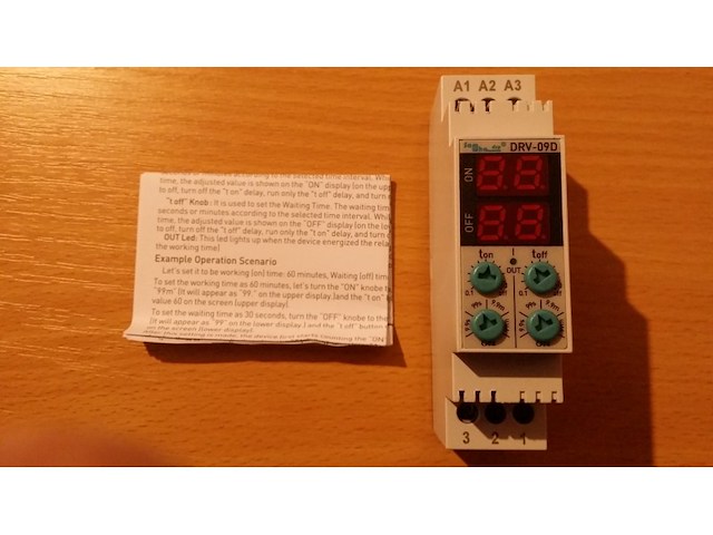
P18 Description General The DRV-09D, DRV-09 flasher relay is designed to be used in places (industry, residence, factory, etc. ) Where two-time (on-off) control is required. Usage and Working Principle Display : lt is shown here when setting the time and counting down the set time. If the operating time is set in minutes, the right most dot on the displays will flash while the device is counting the time. The ON display is reserved for operating time and the OFF display is reserved for waiting time. `ON` Knob: It is used for the working time interval. Interval 9.9 sec. , 99 sec. , 9.9 min. and can be set to 99 minutes (DRV-09D). Interval 9.9 hours. , 99 hours. , 9.9 days. and can be set to 99 days (DRV-09) `OFF` Knob: It is used for the waiting time interval. Interval 9.9 sec. , 99 sec. , 9.9 min. and can be set to 99 minutes (DRV-09D). Interval 9.9 hours. , 99 hours. , 9.9 days. and can be set to 99 days (DRV-09). “ t on` Knob: lt is used to set the Working Time. The working time can be set in seconds or minutes according to the selected time interval. While setting the `t on` time, the adjusted value is shown on the `ON` display (on the upper screen). When set to off, turn off the `t on` delay, run only the ` t off` delay, and turn off the loop function. “ t off` Knob: lt is used to set the Waiting Time. The waiting time can be set in seconds or minutes according to the selected time interval. While setting the `t off` time, the adjusted value is shown on the `OFF` display (on the lower screen). When set to off, turn off the `t off` delay, run only the ` t on` delay, and turn off the loop function. OUT Led: This led lights up when the device energized the relay. (When counting the working time) Example Operation Scenario Let`s set it to be working (on) time:60 minutes, Waiting (off) time: 30 seconds. To set the working time as 60 minutes, let`s turn the `ON` knob to the part that writes `D” (lt will appear as `99. ` on the upper display. ) and the ` t on` knob until see the value 60 on the screen (upper display). To set the waiting time as 30 seconds, turn the `OFF` knob to the part that writes “99s. ` (lt will appear as “99` on the lower display. ) and the `t off` button until see the value 30 on the screen (lower display). After this setting is made, the device first starts counting the`ON` time, the remaining value for the on time is displayed on the `ON` display and the `OUT` led lights up, the relay output is at the 3(NO) contact. When the `ON` time expires, the device starts counting the `OFF` time, the remaining value for the off time is displayed on the `OFF`display and the `OUT` led turns off, the relay output is in contact number 1(NC). The device continues to operate as described above until its power is cut off. NOTE: 1- lf the time interval is changed with the `ON`and / or `OFF` knobs while the device is energized, the device must be de-energized and re-energized in order for the changed time interval to be valid. 2- If the time is changed with the `t on` and/or `t off” knobs while the device is counting time, the device continues to count the new set time. Maintenance Switch off the device and release from connections. Clean the trunk of device with a swab. Don’t use any conductor or chemical might damage the device. Make sure device works after cleaning Warnings -Please use the device according to the manual. -Don’t use the device in wet. -Include a switch and circuit breaker in the assembly. -Put the switch and circuit breaker nearby the device, operator can reach easily. -Mark the switch and circuit breaker as releasing connection for device. Specifications Operating Voltage. .. .. .. .. .. .. :(A1-A2)100-240VAC (A2-A3)12VAC/DC(A2(-), A3(+)) Operating Frequency. .. .. .. : 50/60 Hz. Operating Power. .. .. .. .. .. .. .. : 6VA Operating Temperature. .: -20° C. .. .. +55° C Time interval. .. .. .. .. .. .. .: 0.1sec, - 99min. (DRV-09D) 0.1hours - 99days(DRV-09) Display: .. .. .. .. .. .. .. .. .. .. .. .. .: 2x2 LED Display, 1x LED. Connection Type. .. .. .. .. .: Terminal connection Weight. .. .. .. .. .. .. .. .. .. .. .. .. .. .: Max.80gr. Contact. .. .. .. .. .. .. .. .. .. :5A/250V AC (Resistive Load) Mounting. .. .. .. .. .. .. .. .. .. .. : Assembled on the din rail Operating Altitude. .. .. .. .. .: up to 2000meter Cable Diameter. .. .. .. .. .. .. .. .. : 2,5mm²
-
Mašine i alati chevron_right Ručni alat i rezervni delovi
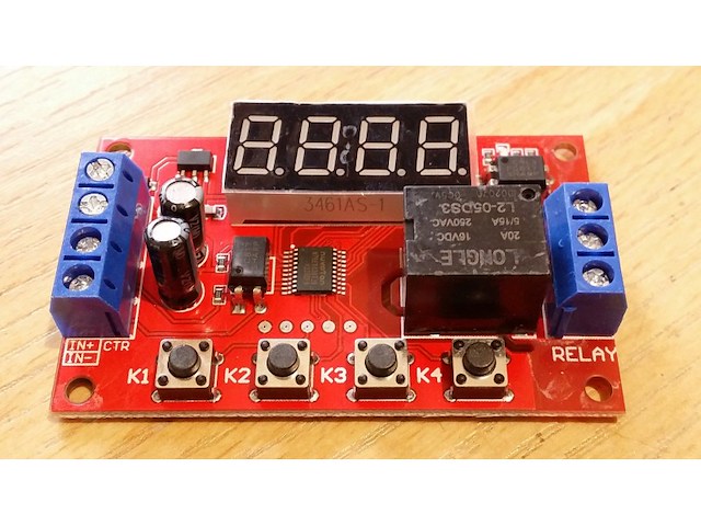
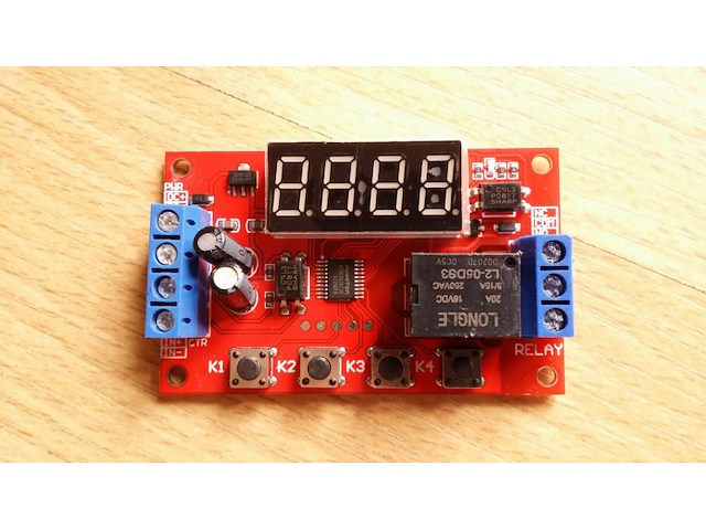
P04 The multi-function relay control module is specially designed for users with many different needs. It adopts a microcontroller as the main control unit and presets 32 kinds of functions, and users can use corresponding specific functions according to actual needs. It can be applied to water pump control, motor control, lamp strip control, solenoid valve control, etc. 1. New upgrade, the module function is increased to 32 kinds, to meet more application needs. 2. The power supply anti-reverse function will not damage the module due to wrong power supply. 3. Timing accuracy to 0.01 seconds timing. 0.1 seconds (minimum) ~ 999 minutes (maximum) optional 4. Low power consumption power saving setting, you can turn off the display area. Product parameters: Product Name: Multi-function time delay relay Relay V number: DC5V/12V/24V optional Input voltage: 5V version: DC5V power supply; 12V version: DC12V power supply; 24V version: DC24V power supply Output load: within 30V DC, maximum 10A. Within 250V, maximum 5A. Trigger signal: 5V version (high level: 5V); 12V version (high level: 12V), 24V version (high level: 24V) The low level is 0V. Quiescent current: 20mA Working current: 60mA Working temperature: -25℃-85℃ Power-off memory: Yes Product weight: ≈26g, product size: 65* 34.3 * 17.5 (MM L*W*H) The manual measurement is for reference only, the actual size is subject to the actual product Product Features: Wiring port description: DC+ Input DC power supply positive DC- Input DC power supply negative IN+ signal input positive IN- signal input negative NO relay normally open interface, the relay is short-circuited with COM when it is engaged, and it is suspended when not engaged; COM relay common terminal interface NC relay normally closed terminal interface, when the relay is not pulled in, it is short-circuited with COM, and it is left floating when pulled in; Instructions for use: Working mode (32 kinds): P-11: In jog mode, there is signal pull-in and no signal disconnect. P-12: Self-locking mode, the state of the relay reverses once after each trigger. P-13: After triggering, the relay will pull in and disconnect after delaying A time; the trigger will be invalid during the delay. P-14: After triggering, the relay will pull in, and it will be disconnected after the delay of A time; the trigger will be re-timed during the delay. P-15: After triggering, the relay will pull in, and it will be disconnected after the delay time A; during the delay time, the accumulated timer will be triggered. P-16: After triggering, the relay will pull in and disconnect after delaying time A; during the delay, a reset will be triggered (relay disconnected). P-17: After triggering, the relay pulls in for the duration of the signal, the input signal disappears, and then disconnects after the delay of A time; during the delay time, the relay is triggered again to keep the pull in, and the timing stops until the last signal disappears, delay A time Then disconnect. P-18: The relay will pull in immediately after power-on, and it will be disconnected after a delay of A second; until the next power-on. P-21: Give the signal, the relay will pull in after the delay of A time. P-22: Give a continuous signal, after the time exceeds A, the relay will pull in; when the signal disappears, the relay will open. P-23: When the signal disappears for more than A time, the relay pulls in; when there is a signal, the relay disconnects. P-24: Give a continuous signal. After the time exceeds A, the relay will pull in; when the signal disappears for more than time A, the relay will open. P-25: Give a continuous signal, the relay pulls in after exceeding A time; give a continuous signal again, the relay turns off after exceeding A time P-26: Give a signal, the relay will disconnect after A time pull-in; after the signal disappears, the relay will stop after A second pull-in. P-27: There is a pulse signal (rising edge or falling edge), the relay is disconnected, there is no pulse signal, the relay pulls in after the delay of A time (continuous high level or continuous low level are considered as no pulse). P-28: After power on, the relay will pull in after the delay time A until power off. The P-31: After power-on, the relay pulls in time A and turns off time B, in an infinite loop; power off stops. P-32: There is a continuous signal, the relay pulls in A time, disconnects B time, infinite loop; the signal disappears, and the loop is terminated. P-33: Give a signal once, the relay pulls in A time, disconnects B time, infinite loop; give another signal to terminate the loop. P-34: After power-on, the relay pulls in after the delay time A, and disconnects after pulling in the time B. P-35: Give a signal, after the delay time A, the relay pulls in and pulls off after the time B pulls in. P-36: Continuous signal is given. After the time A is exceeded, the relay is switched on and disconnected after the time B is switched on; the signal disappears, the timing is cleared, and the relay is turned off. P-37: There is a signal, the relay will be automatically disconnected after the A time is closed, and the B time will be counted after the disconnection. The signal trigger is invalid during the A+B time. P-38: There is a signal, the relay will be automatically disconnected after the time of pull-in A, after the time B is counted after the disconnection, it will be automatically disconnected after the time of pull-in A again. The P-41: The signal does not act; the signal disappears and triggers; the relay absorbs and merges after a delay of A time to disconnect. P-42: The signal disappears. After the delay time A, the relay pulls in; after the delay time B, the relay disconnects. P-43: The signal disappears. After the disappearance exceeds the time A, the relay pulls in; after delaying the time B, the relay opens. P-44: After power-on, the relay pulls in time A and turns off time B; after the cycle C times, the relay turns off and stops. P-45: No action after power on; after the signal is given, the relay pulls in the A time and disconnects the B time; the relay is turned off and stopped after C cycles; when the signal is given, it is executed again. P-46: After the signal is given more than A times, the relay pulls in; keeps pulling in; the power stops. P-47: After the signal exceeds A times, the relay pulls in; when it pulls in for B time, it is disconnected. P-48: During the C time, after continuously giving the signal more than A times, the relay will disconnect and stop after B time. Description table of the position of the decimal point and the time unit it represents: x.xx Decimal point is in the hundreds place, time range 0.01~9.99 seconds xx.x decimal point is in the tenth place, time range 0.1~99.9 seconds xxx has no decimal point, time range is 1~999 seconds xxx. The decimal point is in single digits, the time range is 1~999 minutes Turn off the display: In the non-setting state, press the K4 key to turn off the display, then press it again to turn on. Description of working parameter setting: Hold down the K1 key without letting go, after 2 seconds the display shows P-xx, press K2 and K3 to change the working mode. After selecting the working mode, short press K1 to enter the A time setting, the screen displays Axxx, then press K2 and K3 to modify the A time parameters, K2 and K3 key short press plus or minus 1, long press to quickly add and subtract 10, Press the K4 key to set the position of the decimal point. After setting the A time, press the K1 key to set the B time, the screen displays bxxx, then press the K2 and K3 keys to modify the B time parameters, K2 and K3 keys short press plus or minus 1, long press to quickly add and subtract 10, Press the K4 key to set the position of the decimal point. After setting the B time, (if the mode has the C cycle number parameter), then press the K1 key to set the C cycle number, the screen displays Cxxx, then press the K2 and K3 keys to modify the C cycle number parameter, K2 and K3 keys Short press to increase and decrease by 1, long press to increase and decrease by 10. After setting, press the K1 key once to exit the setting state and save all parameters.
-
Mašine i alati chevron_right Ručni alat i rezervni delovi
P04 The multi-function relay control module is specially designed for users with many different needs. It adopts a microcontroller as the main control unit and presets 32 kinds of functions, and users can use corresponding specific functions according to actual needs. It can be applied to water pump control, motor control, lamp strip control, solenoid valve control, etc. 1. New upgrade, the module function is increased to 32 kinds, to meet more application needs. 2. The power supply anti-reverse function will not damage the module due to wrong power supply. 3. Timing accuracy to 0.01 seconds timing. 0.1 seconds (minimum) ~ 999 minutes (maximum) optional 4. Low power consumption power saving setting, you can turn off the display area. Product parameters: Product Name: Multi-function time delay relay Relay V number: DC5V/12V/24V optional Input voltage: 5V version: DC5V power supply; 12V version: DC12V power supply; 24V version: DC24V power supply Output load: within 30V DC, maximum 10A. Within 250V, maximum 5A. Trigger signal: 5V version (high level: 5V); 12V version (high level: 12V), 24V version (high level: 24V) The low level is 0V. Quiescent current: 20mA Working current: 60mA Working temperature: -25℃-85℃ Power-off memory: Yes Product weight: ≈26g, product size: 65* 34.3 * 17.5 (MM L*W*H) The manual measurement is for reference only, the actual size is subject to the actual product Product Features: Wiring port description: DC+ Input DC power supply positive DC- Input DC power supply negative IN+ signal input positive IN- signal input negative NO relay normally open interface, the relay is short-circuited with COM when it is engaged, and it is suspended when not engaged; COM relay common terminal interface NC relay normally closed terminal interface, when the relay is not pulled in, it is short-circuited with COM, and it is left floating when pulled in; Instructions for use: Working mode (32 kinds): P-11: In jog mode, there is signal pull-in and no signal disconnect. P-12: Self-locking mode, the state of the relay reverses once after each trigger. P-13: After triggering, the relay will pull in and disconnect after delaying A time; the trigger will be invalid during the delay. P-14: After triggering, the relay will pull in, and it will be disconnected after the delay of A time; the trigger will be re-timed during the delay. P-15: After triggering, the relay will pull in, and it will be disconnected after the delay time A; during the delay time, the accumulated timer will be triggered. P-16: After triggering, the relay will pull in and disconnect after delaying time A; during the delay, a reset will be triggered (relay disconnected). P-17: After triggering, the relay pulls in for the duration of the signal, the input signal disappears, and then disconnects after the delay of A time; during the delay time, the relay is triggered again to keep the pull in, and the timing stops until the last signal disappears, delay A time Then disconnect. P-18: The relay will pull in immediately after power-on, and it will be disconnected after a delay of A second; until the next power-on. P-21: Give the signal, the relay will pull in after the delay of A time. P-22: Give a continuous signal, after the time exceeds A, the relay will pull in; when the signal disappears, the relay will open. P-23: When the signal disappears for more than A time, the relay pulls in; when there is a signal, the relay disconnects. P-24: Give a continuous signal. After the time exceeds A, the relay will pull in; when the signal disappears for more than time A, the relay will open. P-25: Give a continuous signal, the relay pulls in after exceeding A time; give a continuous signal again, the relay turns off after exceeding A time P-26: Give a signal, the relay will disconnect after A time pull-in; after the signal disappears, the relay will stop after A second pull-in. P-27: There is a pulse signal (rising edge or falling edge), the relay is disconnected, there is no pulse signal, the relay pulls in after the delay of A time (continuous high level or continuous low level are considered as no pulse). P-28: After power on, the relay will pull in after the delay time A until power off. The P-31: After power-on, the relay pulls in time A and turns off time B, in an infinite loop; power off stops. P-32: There is a continuous signal, the relay pulls in A time, disconnects B time, infinite loop; the signal disappears, and the loop is terminated. P-33: Give a signal once, the relay pulls in A time, disconnects B time, infinite loop; give another signal to terminate the loop. P-34: After power-on, the relay pulls in after the delay time A, and disconnects after pulling in the time B. P-35: Give a signal, after the delay time A, the relay pulls in and pulls off after the time B pulls in. P-36: Continuous signal is given. After the time A is exceeded, the relay is switched on and disconnected after the time B is switched on; the signal disappears, the timing is cleared, and the relay is turned off. P-37: There is a signal, the relay will be automatically disconnected after the A time is closed, and the B time will be counted after the disconnection. The signal trigger is invalid during the A+B time. P-38: There is a signal, the relay will be automatically disconnected after the time of pull-in A, after the time B is counted after the disconnection, it will be automatically disconnected after the time of pull-in A again. The P-41: The signal does not act; the signal disappears and triggers; the relay absorbs and merges after a delay of A time to disconnect. P-42: The signal disappears. After the delay time A, the relay pulls in; after the delay time B, the relay disconnects. P-43: The signal disappears. After the disappearance exceeds the time A, the relay pulls in; after delaying the time B, the relay opens. P-44: After power-on, the relay pulls in time A and turns off time B; after the cycle C times, the relay turns off and stops. P-45: No action after power on; after the signal is given, the relay pulls in the A time and disconnects the B time; the relay is turned off and stopped after C cycles; when the signal is given, it is executed again. P-46: After the signal is given more than A times, the relay pulls in; keeps pulling in; the power stops. P-47: After the signal exceeds A times, the relay pulls in; when it pulls in for B time, it is disconnected. P-48: During the C time, after continuously giving the signal more than A times, the relay will disconnect and stop after B time. Description table of the position of the decimal point and the time unit it represents: x.xx Decimal point is in the hundreds place, time range 0.01~9.99 seconds xx.x decimal point is in the tenth place, time range 0.1~99.9 seconds xxx has no decimal point, time range is 1~999 seconds xxx. The decimal point is in single digits, the time range is 1~999 minutes Turn off the display: In the non-setting state, press the K4 key to turn off the display, then press it again to turn on. Description of working parameter setting: Hold down the K1 key without letting go, after 2 seconds the display shows P-xx, press K2 and K3 to change the working mode. After selecting the working mode, short press K1 to enter the A time setting, the screen displays Axxx, then press K2 and K3 to modify the A time parameters, K2 and K3 key short press plus or minus 1, long press to quickly add and subtract 10, Press the K4 key to set the position of the decimal point. After setting the A time, press the K1 key to set the B time, the screen displays bxxx, then press the K2 and K3 keys to modify the B time parameters, K2 and K3 keys short press plus or minus 1, long press to quickly add and subtract 10, Press the K4 key to set the position of the decimal point. After setting the B time, (if the mode has the C cycle number parameter), then press the K1 key to set the C cycle number, the screen displays Cxxx, then press the K2 and K3 keys to modify the C cycle number parameter, K2 and K3 keys Short press to increase and decrease by 1, long press to increase and decrease by 10. After setting, press the K1 key once to exit the setting state and save all parameters.

-
Mašine i alati chevron_right Ručni alat i rezervni delovi
P08 Description: Switch the modes between cool and heat; Control temperature by setting the temperature setting value and the difference value; Temperature calibration; Refrigerating control output delay protection; Alarm when temperature exceeds temperature limit or when sensor error. Specification: Front panel size: 75x34.5(mm) Mounting size: 71x29(mm) Product size: 75x34.5x85(mm) Sensor length: 1 meter (include the probe) Technical Parameters: Temperature measuring range: -50-99 Celsius Accuracy: 0.1 Celsius Sensor error delay: 1 minute Power supply: AC220V Power consumption: 3w Sensor: NTC sensor(IPC) Relay contact capacity: Cool (10A/220VAC); Heat (10A/220VAC) Ambient temperature: 0-60 Celsius Storage temperature: -30-75 Celsius Relative humidity: 20-85%(No condensate) Indicator light status instruction Indicator light Function Cool indicator light On:Refrigeration starts;Off:Refrigeration stops;Flash:compressor delay Heat indicator light On: heating starts;Off:heating stops Set indicator light On:parameter setting status Key operation instruction: 1. View parameter method: When the controller is working normally, press and release the “▲” button once, display the temperature set value, press and immediately release the “▼” button once to display the temperature difference set value, 2 seconds return to normal temperature display state 2. Set the parameter method When the controller is working normally, press and hold the “S” button for more than 3 seconds to enter the modified parameter mode, The indicator light is on, and the digital tube displays the code `F1` of the first menu item. Press “▲” or “▼” to scroll up or down the menu item and display the menu code, press “S” The key displays the parameter setting value of the current menu. Hold down the “S” key and press and hold “▲” or “ the key can be adjusted up or down and the parameter setting value of the current menu is displayed, while holding down `S` and `▲` The key or “▼” key can quickly up or down and display the parameter settings of the current menu. After the completion, press and release the power button to save the parameter modification and return to the normal temperature display state. If there is no key operation within 0 seconds, the parameter modification will not be saved and return to the normal display state. “Er” is displayed if an error occurs while saving the parameter, and returns to the normal display state after 3 seconds. 3.Repair system data When the machine is powered on, first check whether the parameter setting is normal. If the check is wrong, it will display “ER”. Pressing any key at this time will restore the default parameter settings and work normally. It is recommended to reset the parameters at this time. Operation instruction: Under controller normal working status, press and hold “ ” key for 3s can turn off the controller; Under controller “off” status, press and hold “ ” key for 3s can turn on the controller. Under the controller normal working status, screen displays the current temperature value; also the controller can also switch the working mode between heating and cooling. Controller starts refrigerating with cool indicator light on when the measuring temperature ≥ temperature set value + difference value, and the refrigerating relay is connected; The “Cool” indicator light flashes, it indicates the refrigerating equipment is under compressor delay protect status; when the measuring temperature ≤ temperature set value, the Cool indicator light on, and refrigerating relay disconnects. System starts heating when the measuring temperature value ≤ the temperature set value-difference value, and the “Heat” indicator light on, and the heat relay connects; When the measuring temperature ≥ temperature set value, the “Heat” indicator light is off, and the heat relay disconnects. Menu instruction: Code Function Set range Default F1 Temperature set value -50~99° 10° F2 Difference set value 1~10° 3° F3 Compressor delay time 1~10 minutes 3 minutes F4 Temperature calibration value -10°~10° 0° F5 Fainthearted /Celsius switching Set range 0/1 Error description: Alarm when sensor error: Controller activate the sensor error alarm mode when sensor open circuit or short circuit, all the running status is closed off with the buzzer alarms, and the nixie tube displays “EE”,Press any key can cancel alarm sound, system back to display the normal temperature when the error and the fault is cleared. Alarm when the measuring temperature exceeds temperature measuring range:Controller activates the error alarm function when the measuring temperature exceeds the temperature measuring range, all the running status is closed off with the buzzer alarms, and the nixie tube displays “HH”,Press any key can cancel alarm sound, system back to display the normal temperature when the error and the fault is cleared. Safety Regulations ★Danger: 1.Strictly distinguish the sensor down-lead, power wire and output relay interface from one another, and prohibit wrong connections or overloading the relay. 2.Dangers: Prohibit connecting the wire terminals without electricity cut-off. ★Warning: Prohibit using the machine under the environment of over damp, high temp., strong electromagnetism interference or strong corrosion. ★Notice: 1.The power supply should conform to the voltage value indicated in the instruction. 2.To avoid the interference, the sensor down-lead and power wire should be kept a distance.
-
Mašine i alati chevron_right Ručni alat i rezervni delovi
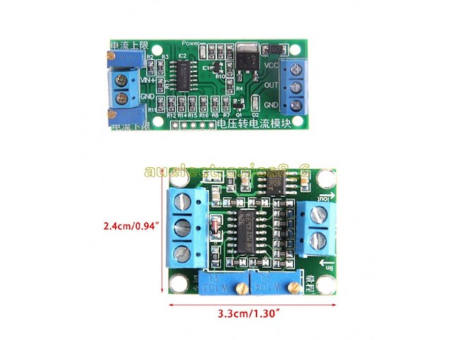
Naponsko strujni i strujno naponski modul 4-20mA. Za prenos podataka na vece daljine i sa vecom sigurnoscu se koristi naposno strujna konverzija u opsegu 4-20mA. Na oba modula se jednim trimerom podesava nula a drugim struja, odnosno napon u odnosu na zeljeni ulazni napon, odnosno struju. U kompletu idu dva modula, naponsko-strujni i strujno-naponski. Current to Voltage Converter 4-20 mA 0-15V Voltage switch current module can convert 0-3.3V / 0-5V / 0-10V / 0-15V voltage signal into 4-20ma current signal; In the process of signal transmission circuit voltage signal will increase transmission distance becomes weak, the transmission can be avoided using weak electric current signal. 1. power supply voltage range of DC 7V ~ 30V 2. the input voltage signal 0 ~ 2.5V, 3.3V, 5V, 10V, 15V. 3. the output current 4-20ma. 4. zero and span can be adjusted (potentiometer adjustment). 5. with the isolated nature of the non-optically isolated. 6. module size: 3.3 * 2.5cm Description: Voltage switch current module can convert 0-5V voltage signal into 4-20mA current signal. In the process of signal transmission circuit voltage signal will become weak with transmission distance increased, the transmission can be avoided using weak electric current signal. Power supply voltage: DC 12V~24V. Input voltsge signal: 0~5V. Output current: 4-20mA. Module size :5.5*2.5cm zero and span can be adiusted (potentiometer adjustment). with the isolated nature of the non-optically isolated. Input and output linear equations: To convert the voltage and output current is a linear relationship, according to the zero point and adjust the range to determine the linear equation, two points to determine a straight line, two points are zero and adjust the range. Iout = K * V + b. For example: 0-10V will be converted to 4-20mA, two points (0.4) and (10.20) which can determine the linear equation I = 1.6 * V +4. Product manual: 1: get the baby power supply module connected to the right side of the three terminals. 2: zero: the conversion voltage signal is adjusted to 0V, adjust the zero reset device to make the output current 4ma. It is best to adjust the potentiometer knob with glue. 3: Tuning: adjust the conversion voltage to the required full-scale voltage (such as 3.3V, 5V, 10V, 15V), will adjust the full potentiometer so that the output current can be 20ma. The adjustment process will find the current output indicator from weak to strong. It is best to adjust the potentiometer knob with glue. 4: input voltage within the range, you can output the corresponding current, and the output current is negative for the power supply. Example of adjustment: For example: the supply voltage of 24V, need to 0-10V into 4-20mA 1: connected to the power supply voltage 24V, 24V positive connected to the right side of the three terminals, the negative side of the right end of the three terminals. 2: Zero: Two short terminals on the left side, adjust the zero knob to make the output (middle three terminals on the right) 4mA. 3: adjust the range: the need for conversion on the left side of the 10V, the left side of the need to convert the voltage of the negative pole. Adjust the span knob so that the output (middle three terminals on the right) is 20mA. 4: to change the voltage in the 0-10V change, the output current in the 4-20mA linear changes.

-
Mašine i alati chevron_right Ručni alat i rezervni delovi
P09 Product description: Single-phase AC active output voltage mutual inductance module equipped with ZMPT101B series of high-precision voltage transformer and high-precision op amp current, easy to 250v within the AC power signal acquisition. Product parameters: Voltage Transformer: Onboard Precision Micro Voltage Transformer Operational amplifier circuit: high-precision on-board amplifier circuit, the signal to do the exact sampling and appropriate compensation and other functions Mode voltage output: the module can measure AC voltage within 250V, the corresponding output mode can be adjusted Output signal: the output signal for the sine wave, the waveform of the median (DC component) Supply voltage: 5-30v Product manual: Adjust the potentiometer can change the amplitude of the output waveform (the adjustment process does not change the middle value) The waveform changes in the range of 0-VCC between; in the process of increasing the amplitude if the waveform distortion, can be appropriately increased by working voltage VCC to solve, If the median value of the waveform is shifted to 0, a capacitor of about 105 pF can be connected in series at the OUT terminal to filter the DC component in the waveform.
-
Mašine i alati chevron_right Ručni alat i rezervni delovi
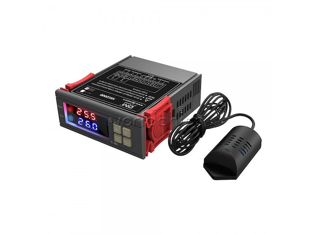
Regulator temperature i vlaznosti vazduha. Moze da radi u modu hladjenja i grejanja kao i ovlazivanja i odvlazivanja vazduha, zavisi kako se podesi. Verzija koja radi na 220V, detaljne karakteristike se vide na jednoj od slika. Setting method: Start value < stop value (program automatically determines working mode is heating/humidifying mode) Setting method: Start value > stop value (the program automatically determines the working mode is cooling/dehumidifying mode) Heating/cooling mode setting Setting mode: setting (starting temperature): Press and hold the ▲ button to start the temperature flashing. Use ▲▼ key to set the starting temperature value. Setting (stop temperature): Press and hold the ▼ button to stop the temperature flashing. Use ▲▼ to set the stop temperature value. Heating use case: control the water heater, heat to 65 ° C to stop, the temperature drops back to 50 ° C and start heating again The first step: heating mode, starting temperature < stop temperature Step 2: Press and hold the ▲ button to start the temperature flashing. Use ▲▼ to set the starting temperature to 50 ° C. Step 3: Press and hold the ▼ button to stop the temperature flashing. Set the stop temperature to 65 ° C with ▲▼ keys, and the setting is completed! Refrigeration use case: use in the farm, the fan is ventilated to 26 ° C to stop, the temperature is raised to 30 ° C and the ventilation is started again. The first step: cooling mode, starting temperature > stop temperature Step 2: Press and hold the ▲ button to start the temperature flashing. Use ▲▼ to set the starting temperature to 30 ° C. The third step: long press the ▼ button to stop the temperature flashing, set the stop temperature to 26 ° C by ▲▼, the setting is completed! Humidification/Dehumidification Mode Settings: Setting (start humidity): Press and hold △ key to start the humidity value flashing. Set the humidity value by △ ▽ key. Set [Stop Humidity]: Press and hold △ key to stop the humidity value flashing, and set the humidity to stop by △ ▽ key value. Humidification example: fresh supermarket humidification, control humidifier 50% RH began to humidify, humidified to 80% RH to stop humidification. Setup steps: Step 1: Press and hold the △ button for 3 seconds to start the humidity value flashing, and set the starting humidity value to 50% RH. Step 2: Press and hold the ▽ button for 3 seconds to stop the humidity value flashing. Set the value to 80% RH. After the setting is completed, the button will be operated for 5 seconds without returning to the normal display state. Dehumidification example: workshop control exhaust dehumidification system, humidity 70% RH starts dehumidification, humidity 40% RH stops dehumidification Setup steps: Step 1: Press and hold the △ button for 3 seconds to start the humidity value flashing, and set the starting humidity value to 40% RH. Step 2: Press and hold the ▽ button for 3 seconds to stop the humidity value flashing, set the value to 70% RH, the setting is completed, the button does not operate for 5 seconds, and automatically returns to the normal display state.

-
Mašine i alati chevron_right Ručni alat i rezervni delovi
SIM808 GPS GSM GPRS bluetooth modul sa antenama za GPS i GSM. Pogodan za mikrokontrolere, Arduino i druge razvojne sisteme. Modul je nov i nekoristen i pored antene za GSM ima i antenu za GPS sa kablom. 1. Three power input interface: DC044 interface and V_IN and a lithium battery interface. Note that: The range of DC044 and the V_IN pin voltage input is 5 - 26V, when use the 5V as the power, be sure that the power supply can provide 2A current. The range of voltage of Lithium battery input power is 3.5 - 4.2V. 2. Switch: It is used to open / close the input power supply for the module. When in use, please confirm the toggle switched to the OPEN state (near the board inside). 3. SMA antenna interface: there is a GSM antenna interface, a GPS antenna interface onboard and a BT antenna interface. 4. Start button: When the board is power on, the LED (PWR) will light up. After a long press (about 2 second) on this button, the other three LEDs will be light. And one of them starts to flash; this suggests that SIM808 is beginning to work now. When the power supply, GSM and GPS antenna and SIM card are connected to the module correctly, the LED will be flash slowly (3Second de 1second light), that indicates that the module is registered to the network, and you can make a call or do something else. 5. TTL serial interface: a TTL level interface. Notice that: The pin of VMCU is used to control the high level of TTL UART, so as to realize to match between 1.25V/3.3V /5V systems. For example, if you want to use the 51 MCU to control this board, the pin of VMCU should be connected the DC5V. And if use the STM32 MCU, the pin of VMCU should be connected the DC3.3V. The pins of RXD is the RXD of SIM808 and the pins of TXD is the TXD of SIM808. The pin of V_IN can connect the Power, the function of this pin has the same function of DC044. 6. USB interface: This interface is just use to update the firmware of SIM808 module. Operation Description: 1. Preparation: SIM808 SHIELD DC9V adapter USB-TTL module or other tools. PC software 2. Hardware configurations 2.1 Connect the USB-TTL to the UART interface USB-TTL SIM808 TXD RXD RXD TXD GND GND 2.2 Insert the valid SIM card to the SIMCARD holder. 2.3 Connect the GPS antenna and GSM antenna to the board Connect the power adapter to the DC044 Interface 2.4 Change the switch 2.6 Press the POWKEY button for 2 second, the SIM808 module will work and the other 3 LEDs will light. Package Included: 1PC*SIM808 Moudle 1PC*GSM Antenna 1PC*GPS Antenna
Istorija cene
Naziv oglasa
Početna cena
Najveća cena
Najniža cena
Nema podataka o istoriji cene

Pretraga: " "
Uspešno ste zapratili pretragu.
Sve zapraćene pretrage možete videti u
korisničkom panelu.