

Pratite promene cene putem maila
- Da bi dobijali obaveštenja o promeni cene potrebno je da kliknete Prati oglas dugme koje se nalazi na dnu svakog oglasa i unesete Vašu mail adresu.
1-23 od 23 rezultata
Broj oglasa
Prikaz
1-23 od 23
1-23 od 23 rezultata
Prikaz
Prati pretragu "b"
Vi se opustite, Gogi će Vas obavestiti kad pronađe nove oglase za tražene ključne reči.
Gogi će vas obavestiti kada pronađe nove oglase.
Režim promene aktivan!
Upravo ste u režimu promene sačuvane pretrage za frazu .
Možete da promenite frazu ili filtere i sačuvate trenutno stanje
-
Mašine i alati chevron_right Ručni alat i rezervni delovi
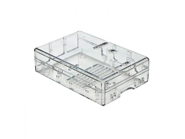
- Kućište za RaspberryPi 3 B i RaspberryPi 3 B+, - Materijal: Polikarbonat, - Boja: transparentno, - Dimenzije: 25.4 x 63.5 x 88.9mm.
-
Mašine i alati chevron_right Ručni alat i rezervni delovi
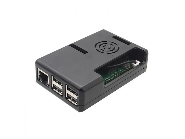
- Kućište za RaspberryPi 3 B i RaspberryPi 3 B+, - Rupa za ventilator, - Materijal: ABS, - Boja: crna, - Dimenzije: 90 x 62 x 26mm, - Težina: 37g.
-
Mašine i alati chevron_right Ručni alat i rezervni delovi
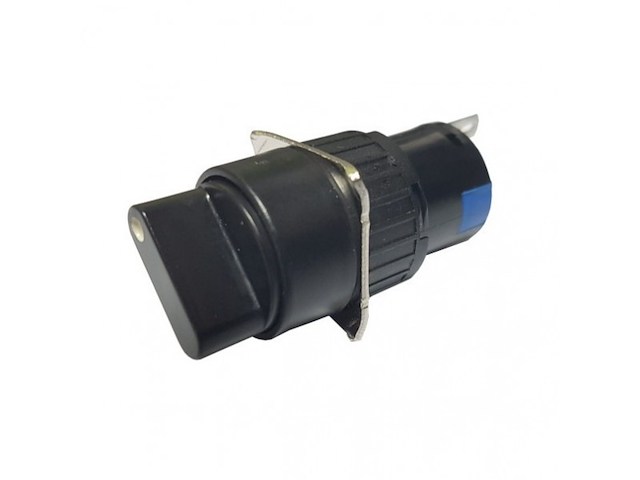
- Funkcija: Prekidač, - Tip: Preklopnik, - Otvor za Ugradnju: Φ16mm, - Boja: Crna, - Kontakti: 1-0 1NO + 1NC, - Zaštita: IP65, - Serija: LA115-C, - Radna Temperatura: -25 ~ +40°C, - Relativna Vlažnost: ≤90%, - Zaštita: IP65, - Maksimalna Moć Preklapanja AC: 0.6A, - Maksimalna Moć Preklapanja DC: 0.6A, - Otpor Kontakta: ≤50mΩ, - Otpor Izolacije: ≥10MΩ, - Broj Preklapanja: 100000.
-
Mašine i alati chevron_right Ručni alat i rezervni delovi
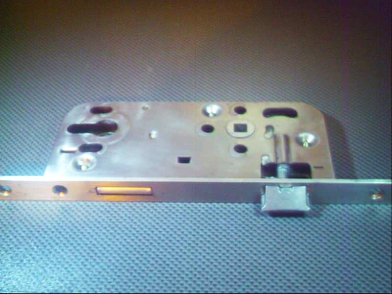
Brava za vrata made in Germany ,kupljena u Nemackoj a prodajem je zato sto je majstor vec ugradio bravu tako da mi je ova visak..
-
Mašine i alati chevron_right Ručni alat i rezervni delovi
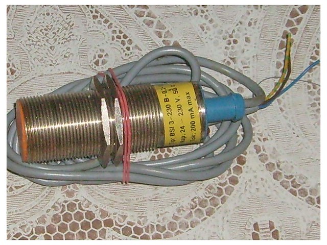
Tip-BSI 3-230 B-0,2-10 D Nap-24-230V,50Hz 200mA max. tri zice 30mm Gorenje
-
Mašine i alati chevron_right Ručni alat i rezervni delovi
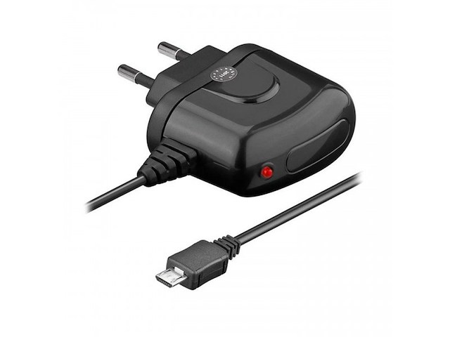
- Ulazni napon: 100 - 240VAC, - Izlazni napon: 5VDC, - Max jačina izlazne struje: 1200mA, - Priključak USB 2.0 Type B micro, - Dužina kabla: 1.4m.

-
Mašine i alati chevron_right Ručni alat i rezervni delovi
Zupčasti kaiš za pogon Black&Decker rendića (hoblarice) oznaka: 4PC PLANER DRIVE BELT 914592 for B&D SR600 SR600K KW750 BD750 DN750 Nov
-
Mašine i alati chevron_right Ručni alat i rezervni delovi
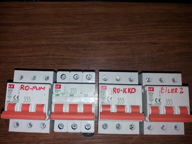
-LS BKN C63 -LS BKN-b C32 -LS BKN C25 -LS BKN C40 -Cena je po komadu. -Za kupovinu svih tropolnih automatskih osiguraca cena je samo 3000 dinara!
-
Mašine i alati chevron_right Ručni alat i rezervni delovi
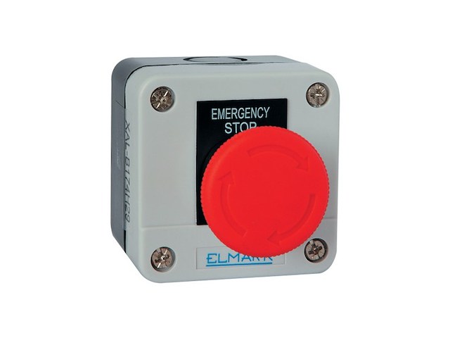
ŠIFRA: 1360 - Kutija sa sigurnosnim (STOP) prekidačem, - Idealna za upravljanje industrijskim mašinama, - Materijal: ABS, - Model: EL1-B, - Stepen IP zaštite: IP44, - Boja: crno/bela, - Sadrži normalno zatvoreni (NC) kontakt, - Dimenzije: 68x68x50mm.
-
Mašine i alati chevron_right Ručni alat i rezervni delovi
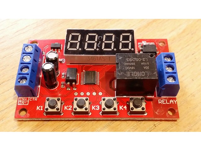
P04 The multi-function relay control module is specially designed for users with many different needs. It adopts a microcontroller as the main control unit and presets 32 kinds of functions, and users can use corresponding specific functions according to actual needs. It can be applied to water pump control, motor control, lamp strip control, solenoid valve control, etc. 1. New upgrade, the module function is increased to 32 kinds, to meet more application needs. 2. The power supply anti-reverse function will not damage the module due to wrong power supply. 3. Timing accuracy to 0.01 seconds timing. 0.1 seconds (minimum) ~ 999 minutes (maximum) optional 4. Low power consumption power saving setting, you can turn off the display area. Product parameters: Product Name: Multi-function time delay relay Relay V number: DC5V/12V/24V optional Input voltage: 5V version: DC5V power supply; 12V version: DC12V power supply; 24V version: DC24V power supply Output load: within 30V DC, maximum 10A. Within 250V, maximum 5A. Trigger signal: 5V version (high level: 5V); 12V version (high level: 12V), 24V version (high level: 24V) The low level is 0V. Quiescent current: 20mA Working current: 60mA Working temperature: -25℃-85℃ Power-off memory: Yes Product weight: ≈26g, product size: 65* 34.3 * 17.5 (MM L*W*H) The manual measurement is for reference only, the actual size is subject to the actual product Product Features: Wiring port description: DC+ Input DC power supply positive DC- Input DC power supply negative IN+ signal input positive IN- signal input negative NO relay normally open interface, the relay is short-circuited with COM when it is engaged, and it is suspended when not engaged; COM relay common terminal interface NC relay normally closed terminal interface, when the relay is not pulled in, it is short-circuited with COM, and it is left floating when pulled in; Instructions for use: Working mode (32 kinds): P-11: In jog mode, there is signal pull-in and no signal disconnect. P-12: Self-locking mode, the state of the relay reverses once after each trigger. P-13: After triggering, the relay will pull in and disconnect after delaying A time; the trigger will be invalid during the delay. P-14: After triggering, the relay will pull in, and it will be disconnected after the delay of A time; the trigger will be re-timed during the delay. P-15: After triggering, the relay will pull in, and it will be disconnected after the delay time A; during the delay time, the accumulated timer will be triggered. P-16: After triggering, the relay will pull in and disconnect after delaying time A; during the delay, a reset will be triggered (relay disconnected). P-17: After triggering, the relay pulls in for the duration of the signal, the input signal disappears, and then disconnects after the delay of A time; during the delay time, the relay is triggered again to keep the pull in, and the timing stops until the last signal disappears, delay A time Then disconnect. P-18: The relay will pull in immediately after power-on, and it will be disconnected after a delay of A second; until the next power-on. P-21: Give the signal, the relay will pull in after the delay of A time. P-22: Give a continuous signal, after the time exceeds A, the relay will pull in; when the signal disappears, the relay will open. P-23: When the signal disappears for more than A time, the relay pulls in; when there is a signal, the relay disconnects. P-24: Give a continuous signal. After the time exceeds A, the relay will pull in; when the signal disappears for more than time A, the relay will open. P-25: Give a continuous signal, the relay pulls in after exceeding A time; give a continuous signal again, the relay turns off after exceeding A time P-26: Give a signal, the relay will disconnect after A time pull-in; after the signal disappears, the relay will stop after A second pull-in. P-27: There is a pulse signal (rising edge or falling edge), the relay is disconnected, there is no pulse signal, the relay pulls in after the delay of A time (continuous high level or continuous low level are considered as no pulse). P-28: After power on, the relay will pull in after the delay time A until power off. The P-31: After power-on, the relay pulls in time A and turns off time B, in an infinite loop; power off stops. P-32: There is a continuous signal, the relay pulls in A time, disconnects B time, infinite loop; the signal disappears, and the loop is terminated. P-33: Give a signal once, the relay pulls in A time, disconnects B time, infinite loop; give another signal to terminate the loop. P-34: After power-on, the relay pulls in after the delay time A, and disconnects after pulling in the time B. P-35: Give a signal, after the delay time A, the relay pulls in and pulls off after the time B pulls in. P-36: Continuous signal is given. After the time A is exceeded, the relay is switched on and disconnected after the time B is switched on; the signal disappears, the timing is cleared, and the relay is turned off. P-37: There is a signal, the relay will be automatically disconnected after the A time is closed, and the B time will be counted after the disconnection. The signal trigger is invalid during the A+B time. P-38: There is a signal, the relay will be automatically disconnected after the time of pull-in A, after the time B is counted after the disconnection, it will be automatically disconnected after the time of pull-in A again. The P-41: The signal does not act; the signal disappears and triggers; the relay absorbs and merges after a delay of A time to disconnect. P-42: The signal disappears. After the delay time A, the relay pulls in; after the delay time B, the relay disconnects. P-43: The signal disappears. After the disappearance exceeds the time A, the relay pulls in; after delaying the time B, the relay opens. P-44: After power-on, the relay pulls in time A and turns off time B; after the cycle C times, the relay turns off and stops. P-45: No action after power on; after the signal is given, the relay pulls in the A time and disconnects the B time; the relay is turned off and stopped after C cycles; when the signal is given, it is executed again. P-46: After the signal is given more than A times, the relay pulls in; keeps pulling in; the power stops. P-47: After the signal exceeds A times, the relay pulls in; when it pulls in for B time, it is disconnected. P-48: During the C time, after continuously giving the signal more than A times, the relay will disconnect and stop after B time. Description table of the position of the decimal point and the time unit it represents: x.xx Decimal point is in the hundreds place, time range 0.01~9.99 seconds xx.x decimal point is in the tenth place, time range 0.1~99.9 seconds xxx has no decimal point, time range is 1~999 seconds xxx. The decimal point is in single digits, the time range is 1~999 minutes Turn off the display: In the non-setting state, press the K4 key to turn off the display, then press it again to turn on. Description of working parameter setting: Hold down the K1 key without letting go, after 2 seconds the display shows P-xx, press K2 and K3 to change the working mode. After selecting the working mode, short press K1 to enter the A time setting, the screen displays Axxx, then press K2 and K3 to modify the A time parameters, K2 and K3 key short press plus or minus 1, long press to quickly add and subtract 10, Press the K4 key to set the position of the decimal point. After setting the A time, press the K1 key to set the B time, the screen displays bxxx, then press the K2 and K3 keys to modify the B time parameters, K2 and K3 keys short press plus or minus 1, long press to quickly add and subtract 10, Press the K4 key to set the position of the decimal point. After setting the B time, (if the mode has the C cycle number parameter), then press the K1 key to set the C cycle number, the screen displays Cxxx, then press the K2 and K3 keys to modify the C cycle number parameter, K2 and K3 keys Short press to increase and decrease by 1, long press to increase and decrease by 10. After setting, press the K1 key once to exit the setting state and save all parameters.
-
Mašine i alati chevron_right Ručni alat i rezervni delovi
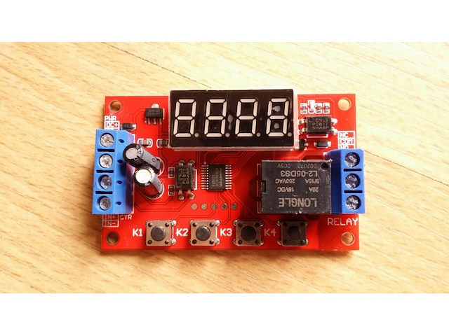
P04 The multi-function relay control module is specially designed for users with many different needs. It adopts a microcontroller as the main control unit and presets 32 kinds of functions, and users can use corresponding specific functions according to actual needs. It can be applied to water pump control, motor control, lamp strip control, solenoid valve control, etc. 1. New upgrade, the module function is increased to 32 kinds, to meet more application needs. 2. The power supply anti-reverse function will not damage the module due to wrong power supply. 3. Timing accuracy to 0.01 seconds timing. 0.1 seconds (minimum) ~ 999 minutes (maximum) optional 4. Low power consumption power saving setting, you can turn off the display area. Product parameters: Product Name: Multi-function time delay relay Relay V number: DC5V/12V/24V optional Input voltage: 5V version: DC5V power supply; 12V version: DC12V power supply; 24V version: DC24V power supply Output load: within 30V DC, maximum 10A. Within 250V, maximum 5A. Trigger signal: 5V version (high level: 5V); 12V version (high level: 12V), 24V version (high level: 24V) The low level is 0V. Quiescent current: 20mA Working current: 60mA Working temperature: -25℃-85℃ Power-off memory: Yes Product weight: ≈26g, product size: 65* 34.3 * 17.5 (MM L*W*H) The manual measurement is for reference only, the actual size is subject to the actual product Product Features: Wiring port description: DC+ Input DC power supply positive DC- Input DC power supply negative IN+ signal input positive IN- signal input negative NO relay normally open interface, the relay is short-circuited with COM when it is engaged, and it is suspended when not engaged; COM relay common terminal interface NC relay normally closed terminal interface, when the relay is not pulled in, it is short-circuited with COM, and it is left floating when pulled in; Instructions for use: Working mode (32 kinds): P-11: In jog mode, there is signal pull-in and no signal disconnect. P-12: Self-locking mode, the state of the relay reverses once after each trigger. P-13: After triggering, the relay will pull in and disconnect after delaying A time; the trigger will be invalid during the delay. P-14: After triggering, the relay will pull in, and it will be disconnected after the delay of A time; the trigger will be re-timed during the delay. P-15: After triggering, the relay will pull in, and it will be disconnected after the delay time A; during the delay time, the accumulated timer will be triggered. P-16: After triggering, the relay will pull in and disconnect after delaying time A; during the delay, a reset will be triggered (relay disconnected). P-17: After triggering, the relay pulls in for the duration of the signal, the input signal disappears, and then disconnects after the delay of A time; during the delay time, the relay is triggered again to keep the pull in, and the timing stops until the last signal disappears, delay A time Then disconnect. P-18: The relay will pull in immediately after power-on, and it will be disconnected after a delay of A second; until the next power-on. P-21: Give the signal, the relay will pull in after the delay of A time. P-22: Give a continuous signal, after the time exceeds A, the relay will pull in; when the signal disappears, the relay will open. P-23: When the signal disappears for more than A time, the relay pulls in; when there is a signal, the relay disconnects. P-24: Give a continuous signal. After the time exceeds A, the relay will pull in; when the signal disappears for more than time A, the relay will open. P-25: Give a continuous signal, the relay pulls in after exceeding A time; give a continuous signal again, the relay turns off after exceeding A time P-26: Give a signal, the relay will disconnect after A time pull-in; after the signal disappears, the relay will stop after A second pull-in. P-27: There is a pulse signal (rising edge or falling edge), the relay is disconnected, there is no pulse signal, the relay pulls in after the delay of A time (continuous high level or continuous low level are considered as no pulse). P-28: After power on, the relay will pull in after the delay time A until power off. The P-31: After power-on, the relay pulls in time A and turns off time B, in an infinite loop; power off stops. P-32: There is a continuous signal, the relay pulls in A time, disconnects B time, infinite loop; the signal disappears, and the loop is terminated. P-33: Give a signal once, the relay pulls in A time, disconnects B time, infinite loop; give another signal to terminate the loop. P-34: After power-on, the relay pulls in after the delay time A, and disconnects after pulling in the time B. P-35: Give a signal, after the delay time A, the relay pulls in and pulls off after the time B pulls in. P-36: Continuous signal is given. After the time A is exceeded, the relay is switched on and disconnected after the time B is switched on; the signal disappears, the timing is cleared, and the relay is turned off. P-37: There is a signal, the relay will be automatically disconnected after the A time is closed, and the B time will be counted after the disconnection. The signal trigger is invalid during the A+B time. P-38: There is a signal, the relay will be automatically disconnected after the time of pull-in A, after the time B is counted after the disconnection, it will be automatically disconnected after the time of pull-in A again. The P-41: The signal does not act; the signal disappears and triggers; the relay absorbs and merges after a delay of A time to disconnect. P-42: The signal disappears. After the delay time A, the relay pulls in; after the delay time B, the relay disconnects. P-43: The signal disappears. After the disappearance exceeds the time A, the relay pulls in; after delaying the time B, the relay opens. P-44: After power-on, the relay pulls in time A and turns off time B; after the cycle C times, the relay turns off and stops. P-45: No action after power on; after the signal is given, the relay pulls in the A time and disconnects the B time; the relay is turned off and stopped after C cycles; when the signal is given, it is executed again. P-46: After the signal is given more than A times, the relay pulls in; keeps pulling in; the power stops. P-47: After the signal exceeds A times, the relay pulls in; when it pulls in for B time, it is disconnected. P-48: During the C time, after continuously giving the signal more than A times, the relay will disconnect and stop after B time. Description table of the position of the decimal point and the time unit it represents: x.xx Decimal point is in the hundreds place, time range 0.01~9.99 seconds xx.x decimal point is in the tenth place, time range 0.1~99.9 seconds xxx has no decimal point, time range is 1~999 seconds xxx. The decimal point is in single digits, the time range is 1~999 minutes Turn off the display: In the non-setting state, press the K4 key to turn off the display, then press it again to turn on. Description of working parameter setting: Hold down the K1 key without letting go, after 2 seconds the display shows P-xx, press K2 and K3 to change the working mode. After selecting the working mode, short press K1 to enter the A time setting, the screen displays Axxx, then press K2 and K3 to modify the A time parameters, K2 and K3 key short press plus or minus 1, long press to quickly add and subtract 10, Press the K4 key to set the position of the decimal point. After setting the A time, press the K1 key to set the B time, the screen displays bxxx, then press the K2 and K3 keys to modify the B time parameters, K2 and K3 keys short press plus or minus 1, long press to quickly add and subtract 10, Press the K4 key to set the position of the decimal point. After setting the B time, (if the mode has the C cycle number parameter), then press the K1 key to set the C cycle number, the screen displays Cxxx, then press the K2 and K3 keys to modify the C cycle number parameter, K2 and K3 keys Short press to increase and decrease by 1, long press to increase and decrease by 10. After setting, press the K1 key once to exit the setting state and save all parameters.
-
Mašine i alati chevron_right Ručni alat i rezervni delovi
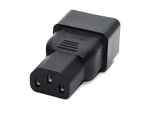
- Adapter C20 utikač - C13 utičnica, - Radni napon: 250V, - Maksimalna jačina struje: 10A, - Snaga: 4000W, - Materijal izrade: metal, plastika, - Dimenzije: 33.5 (A) x 61.5 (B) x 23 (C) x 20.5mm (D), - Masa: 43g, - Boja: crna.
-
Mašine i alati chevron_right Ručni alat i rezervni delovi
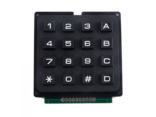
ŠIFRA: 587 - Matrična tastatura sa 16 tastera, - Materijal: plastika, - Boja: crna, - Idealna za razne projekte sa mikrokontrolerima, `Arduino` i drugim razvojnim sistemima, - Sadrži deset numeričkih tastera (0-9), četiri alfanumerička tastera (A, B, C i D) i dva tastear sa specijalnim karakterima (`*` i `*#`), - Napon napajanja: 3-5VDC, - Dimenzije: 69x76x8mm, - Konektor: 10 pinova, - Životni vek: 1 000 000 uključenja.
-
Mašine i alati chevron_right Ručni alat i rezervni delovi
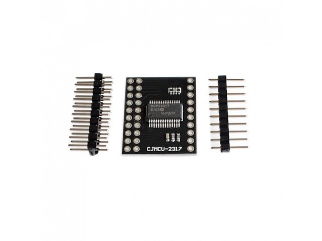
MCP23017 is capable of converting 16-bit parallel data to serial data of the IIC interface and converting each other. Features: 1.16-Bit Remote Bidirectional I/O Port. 2. Three Hardware Address Pins to Allow Up to Eight Devices On the Bus. 3. Configurable Interrupt Output Pins. 4. Configurable as active-high, active-low or open-drain. 5. INTA and INTB Can Be Configured to Operate Independently or Together. Specifications: Model: MCP23017 Material: Electrical components Color: Black Operating temperature range: -40~85 Degree Working voltage: 1.8~5.5V IIC communication frequency: up to 1.7MHz Working current: 1uA VCC: Power supply pin INTA: A port interrupt output INTB: B port terminal output SCL: IIC clock signal line SDA: IIC data signal line RESET: level reset device A0, A1, A2: IIC device address configuration pins The default is 0100000x, and the IIC bus can expand 8 identical devices. GPA0~GPA7: A port 8-bit input and output pin (default input mode) GPB0~GPB7: B port 8-bit input and output pin (default input mode)

-
Mašine i alati chevron_right Ručni alat i rezervni delovi
Temperaturna sonda -40-110℃- NTC tip sa M8 zavrtnjom Karakteristike: - Temperatura: -40-110 ℃ - Tip: NTC (10kohm±1% 3950) - Dužina: 1 m - Dimenzije ispitnoga dela: M8 navoj - Dvožična veza - Konektor za priključenje - Vodootporna - B konstanta 3950K -/+ 1% - Tipična disipacija: 5 mW/°C - Otpornost izolacije: > 100 MOhm - Napon u piku: 1800V AC - 1ma - 1 sekunda - Naprezanje: 9.8 N (1kgF) 1 minut bez deformacije
-
Mašine i alati chevron_right Ručni alat i rezervni delovi
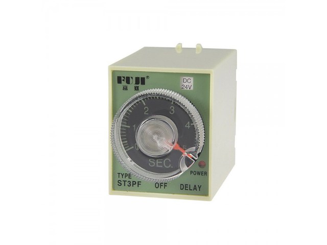
Vremenski relej sa zakašnjenjem pri uključivanju! Nakon dobijanja upravljačkog napona kasni sa pomerajem svojih kontakata za unapred zadano vreme. - Artikal: rele vremenski (FULI), - Model / Tip: ST3P A-B, - Nazivni Napon: 200-220 V AC, - Nazivna Struja: 3 A, - Vremenski Interval: 1s/10s/60s/6min., - Broj Pinova: 8, - Način / Tip Montaže: na podnozje PF083, - Temperatura Okruženja (ºC): -40°C do + 60°C, - IP Zaštita: IP 20.
-
Mašine i alati chevron_right Ručni alat i rezervni delovi
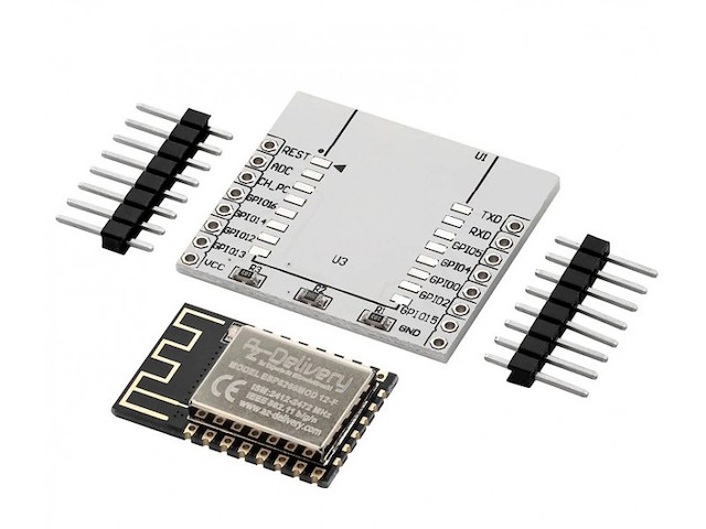
- WiFi modul je baziran na ESP8266 SoC sa integrisanim TCP/IP protokolom, - TTL serijski komuikacioni interfejs i parametri mogu biti podešeni preko AT komandi, - Široko je u upotrebi u umrežavanju, projektima pametne kuće kada je povezan na wifi ruter, - Radni napon komunikacionog interfejsa: 3.3V, - Tip antene: unutrašnja PCB antena, - Wireless Network Mode: stanica / softAP / SoftAP + stanica, - WiFi standardi: 802.11 b / g / n., - Podržava WPA / WPA2 sigurnosne modove.
-
Mašine i alati chevron_right Ručni alat i rezervni delovi
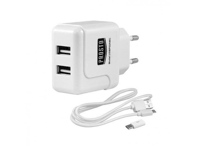
ŠIFRA: 1029 - Univerzalni punjač sa dva USB priključka, - Idealan za punjenje akumulatora prenosnih uređaja (muzičke plejere, navigacije, mobilne telefone...), - U kompletu sa punjačem se isporučuje i USB priključni kabl dužine 1 m i adapter sa mikro USB B na mikro USB C, - Poseduje zaštitu od kratkog spoja, pregrevanja i preopterećenja, - Uređaj koji želite priključiti treba da je radnog napona od 5V i maksimalne potrošnje do 2A, - Ulazni napon: 230VAC/50Hz/0.3A, - Izlazni napon: 5VDC, - Maksimalna izlazna struja 2A (1A po izlazu kada se oba izlaza koriste istovremeno), - Maksimalna izlazna snaga: 10W, - Priključci: 2xUSB utičnica.
-
Mašine i alati chevron_right Ručni alat i rezervni delovi
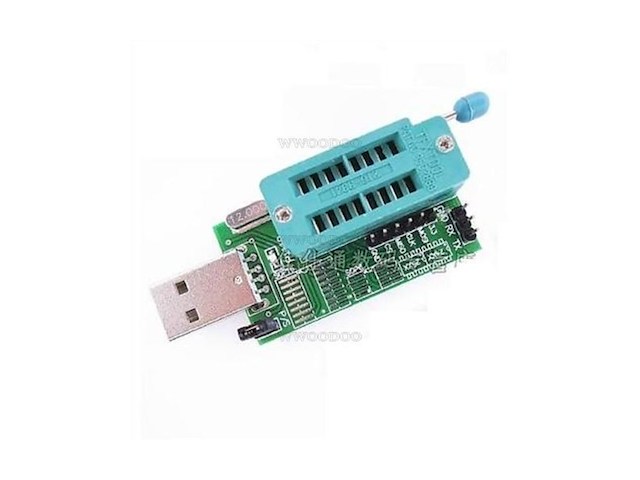
Ovaj programator je namenjen programiranju 8-pinskih SPI fleš memorija kao što su W25Q32, W25X80 i mnoge druge. Pored svoje osnovne mogućnosti, ovaj programator podržava i programiranje I2C serijskih EEPROM-a familije 24CXX ( 24C01, 24C02, 04, 08 . . . 24C1024 ). Spisak podržanih kola: http: //bleha. net/sw/usbspifl. txt Komplet sadrži: - Zalemljen i ispitan modul programatora - 2 različite SMD adapter ploče USB 2.0 interface, The speed of reading and writing is very fast. support WIN98 ,WINME ,WIN2K ,WINXP ,VISTA ,WIN7 32bit/64bit Speed: 2-3M/min Using recoverable automatically fuse the event of the the chips short-circuit or chip installed anti will automatically power off ( indicator turns off ) to avoid motherboard , programmer and chip burn out , short circuit exclude automatic recovery Working Voltage: 5V mini-B connecor CH341A as the main chip, this module has good Quantity Support 24,25 series chips USB to TTL could be used to download code Two Function: TTL and Program Power indicator Recoverable fuse automatically: when the chip is in short-circuit or installed wrongly, the fuse will be used to protected the chip unless the error has been corrected. POGLEDAJTE JOS NASIH OGLASA! NAJJEFTINIJE U SRBIJI - PROVERENO!
-
Mašine i alati chevron_right Ručni alat i rezervni delovi
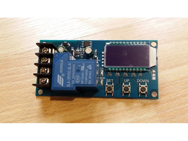
P12 1. Support Lead-acid battery and Acting Battery,voltage range:6V~60V; 2. Can display voltage,percent of battery,charging time at the same time through LCD; 3. The function is very powerful,realizes the automatic charge control, the control charge time, also may set up and uploads the corresponding parameter through the serial port; Function description 1. Automatic Charge control function: By setting the volt-HI:`UP` volt-LI:`dn`;When the battery voltage is below the volt-LI:`dn`,the relay leads,the charger begins to charge the battery;when the battery voltage is up to volt-HI:`UP`,the relay is diconnected and the automatic charge is completed once; 2. Charge Time Control Function: How to turn on the time control function? After entering the parameter set, set the parameter op is non-zero, then turn on the time control function, op default parameter is:--:--h, the default does not turn on time control function; After the opening Time control function (OP is non-zero), when the battery voltage is the lower volt-LI`dn`, the charger began to charge the battery, the system began to clock; During the timing, the battery voltage ≥ volt-HI`UP`, relay disconnect; If the OP time is up, the battery voltage is still the lower volt-LI`dn`, the relay keeps the conduction, automatically closes the charge time control function, and flashes the H:ER to remind the user, the time parameter setting is unreasonable; Press any key to stop flashing; Note: Time format: 00:59 (00 for hours, 59 for minutes) The maximum time is 99:59, which is 100 hours. 3. Serial data upload and parameter setting function: The system supports UART data upload and parameter setting UART:115200,8,1 Cmd Func on Relays enable to open off Relays disable to open start Start data upload stop Stop data upload read Read the param setting dw10.0 Set volt-LI:`dn` up20.0 Set volt-HI:`UP` xx:xx Set the charge time OP 00:00 stop charge time Data Upload message Format: Battery voltage + battery percent + charge time + charge status 12.0V,020%,00:10,OP Parameter Setting a) Press and hold the SET key to enter the setting interface; b) Switch the parameters you want to set by short press SET; c) After the selection of parameters, can be set by the UP/DOWN key to support the short press, long press (fast increase or decrease); To set other parameters, repeat step b, c); d) After all parameters are set, long press set key to exit and save; The Key Function Description: In the Run interface (main interface): Short press SET button to display the current set of parameters; Short press UP button, toggle display charge percentage and charging time; Short Press DOWN button, select Turn on/off relay enabling, if the relay can be closed, will show ` off ` as a reminder; Long press UP button, switch low power state on:No operation in 10 minutes turn off backlight OFF: Backlight is always bright Long press SET button,enter the parameter settings. Calculation of voltage percentage: voltage percentage = battery voltage/(volt-HI – volt-LI) Additional Features a) Charging time recording function: not open charging time control, the product will record a full time, when the entry time display interface, flashing display charging time, and then exit time display interface or next charge to open (relay conduction) when empty; b) Automatic parameter detection: When the parameters are set, exit, if volt-LI dn≥ volt-HI UP, the system will flash display `ERR` as a reminder; c) Battery Access detection: This product attached to the battery, if not connected to the battery, the system will be shown in the downlink `NbE` as a reminder Analysis of common failures Q: How much is suitable for V level use? How much v voltage does this module fit? A: This section is suitable for the minimum 6V, the highest 60V voltage range, the maximum expenditure level 48V, because 48V battery full of electricity in 60V, and then a high fever, if your battery is higher than 48V, please select other section. Q: The power of the subsequent electrical appliances snapped! LED flashing? A: This is because your charging current is too large or the battery capacity is too small to cause a power to immediately reach the voltage limit, relay disconnect, disconnect, the voltage and quickly down to the lower voltage, and began to recharge, cycle, at this time you want to reduce the charging current only line, Usually the charging current is the battery capacity of the very 1 to 1.5, such as 20AH battery charging current generally around 2-3a! Note that a large current charge will cause the battery fever accelerated aging, drum kits and even explosions! Q: What control mode? Can I cycle the charge automatically? Can I use the side charge? Can I limit the flow? A: This is voltage control, For example, set the voltage limit of 12.0V, voltage up to 14.5V, voltage charge to 14.5V this value on the power off, voltage down to the 12.0V relay closed and start charging, can be filled with side, voltage control mode only to turn off and open, can not limit the flow, charging current completely depends on your charger! Q: Input 12V can or not charge 24V battery, or enter 48V can give 12V battery charge? A:This is a simple voltage controller, only play the role of switch, can not swing to the battery charge, so you want to give what battery charge to be ready what kind of charger! It`s necessary!
-
Mašine i alati chevron_right Ručni alat i rezervni delovi
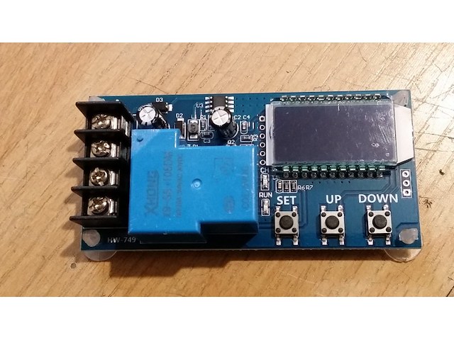
P01 1. Support Lead-acid battery and Acting Battery,voltage range:6V~60V; 2. Can display voltage,percent of battery,charging time at the same time through LCD; 3. The function is very powerful,realizes the automatic charge control, the control charge time, also may set up and uploads the corresponding parameter through the serial port; Function description 1. Automatic Charge control function: By setting the volt-HI:`UP` volt-LI:`dn`;When the battery voltage is below the volt-LI:`dn`,the relay leads,the charger begins to charge the battery;when the battery voltage is up to volt-HI:`UP`,the relay is diconnected and the automatic charge is completed once; 2. Charge Time Control Function: How to turn on the time control function? After entering the parameter set, set the parameter op is non-zero, then turn on the time control function, op default parameter is:--:--h, the default does not turn on time control function; After the opening Time control function (OP is non-zero), when the battery voltage is the lower volt-LI`dn`, the charger began to charge the battery, the system began to clock; During the timing, the battery voltage ≥ volt-HI`UP`, relay disconnect; If the OP time is up, the battery voltage is still the lower volt-LI`dn`, the relay keeps the conduction, automatically closes the charge time control function, and flashes the H:ER to remind the user, the time parameter setting is unreasonable; Press any key to stop flashing; Note: Time format: 00:59 (00 for hours, 59 for minutes) The maximum time is 99:59, which is 100 hours. 3. Serial data upload and parameter setting function: The system supports UART data upload and parameter setting UART:115200,8,1 Cmd Func on Relays enable to open off Relays disable to open start Start data upload stop Stop data upload read Read the param setting dw10.0 Set volt-LI:`dn` up20.0 Set volt-HI:`UP` xx:xx Set the charge time OP 00:00 stop charge time Data Upload message Format: Battery voltage + battery percent + charge time + charge status 12.0V,020%,00:10,OP Parameter Setting a) Press and hold the SET key to enter the setting interface; b) Switch the parameters you want to set by short press SET; c) After the selection of parameters, can be set by the UP/DOWN key to support the short press, long press (fast increase or decrease); To set other parameters, repeat step b, c); d) After all parameters are set, long press set key to exit and save; The Key Function Description: In the Run interface (main interface): Short press SET button to display the current set of parameters; Short press UP button, toggle display charge percentage and charging time; Short Press DOWN button, select Turn on/off relay enabling, if the relay can be closed, will show ` off ` as a reminder; Long press UP button, switch low power state on:No operation in 10 minutes turn off backlight OFF: Backlight is always bright Long press SET button,enter the parameter settings. Calculation of voltage percentage: voltage percentage = battery voltage/(volt-HI – volt-LI) Additional Features a) Charging time recording function: not open charging time control, the product will record a full time, when the entry time display interface, flashing display charging time, and then exit time display interface or next charge to open (relay conduction) when empty; b) Automatic parameter detection: When the parameters are set, exit, if volt-LI dn≥ volt-HI UP, the system will flash display `ERR` as a reminder; c) Battery Access detection: This product attached to the battery, if not connected to the battery, the system will be shown in the downlink `NbE` as a reminder Analysis of common failures Q: How much is suitable for V level use? How much v voltage does this module fit? A: This section is suitable for the minimum 6V, the highest 60V voltage range, the maximum expenditure level 48V, because 48V battery full of electricity in 60V, and then a high fever, if your battery is higher than 48V, please select other section. Q: The power of the subsequent electrical appliances snapped! LED flashing? A: This is because your charging current is too large or the battery capacity is too small to cause a power to immediately reach the voltage limit, relay disconnect, disconnect, the voltage and quickly down to the lower voltage, and began to recharge, cycle, at this time you want to reduce the charging current only line, Usually the charging current is the battery capacity of the very 1 to 1.5, such as 20AH battery charging current generally around 2-3a! Note that a large current charge will cause the battery fever accelerated aging, drum kits and even explosions! Q: What control mode? Can I cycle the charge automatically? Can I use the side charge? Can I limit the flow? A: This is voltage control, For example, set the voltage limit of 12.0V, voltage up to 14.5V, voltage charge to 14.5V this value on the power off, voltage down to the 12.0V relay closed and start charging, can be filled with side, voltage control mode only to turn off and open, can not limit the flow, charging current completely depends on your charger! Q: Input 12V can or not charge 24V battery, or enter 48V can give 12V battery charge? A:This is a simple voltage controller, only play the role of switch, can not swing to the battery charge, so you want to give what battery charge to be ready what kind of charger! It`s necessary!
-
Mašine i alati chevron_right Ručni alat i rezervni delovi
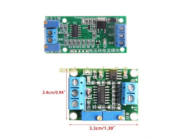
Naponsko strujni i strujno naponski modul 4-20mA. Za prenos podataka na vece daljine i sa vecom sigurnoscu se koristi naposno strujna konverzija u opsegu 4-20mA. Na oba modula se jednim trimerom podesava nula a drugim struja, odnosno napon u odnosu na zeljeni ulazni napon, odnosno struju. U kompletu idu dva modula, naponsko-strujni i strujno-naponski. Current to Voltage Converter 4-20 mA 0-15V Voltage switch current module can convert 0-3.3V / 0-5V / 0-10V / 0-15V voltage signal into 4-20ma current signal; In the process of signal transmission circuit voltage signal will increase transmission distance becomes weak, the transmission can be avoided using weak electric current signal. 1. power supply voltage range of DC 7V ~ 30V 2. the input voltage signal 0 ~ 2.5V, 3.3V, 5V, 10V, 15V. 3. the output current 4-20ma. 4. zero and span can be adjusted (potentiometer adjustment). 5. with the isolated nature of the non-optically isolated. 6. module size: 3.3 * 2.5cm Description: Voltage switch current module can convert 0-5V voltage signal into 4-20mA current signal. In the process of signal transmission circuit voltage signal will become weak with transmission distance increased, the transmission can be avoided using weak electric current signal. Power supply voltage: DC 12V~24V. Input voltsge signal: 0~5V. Output current: 4-20mA. Module size :5.5*2.5cm zero and span can be adiusted (potentiometer adjustment). with the isolated nature of the non-optically isolated. Input and output linear equations: To convert the voltage and output current is a linear relationship, according to the zero point and adjust the range to determine the linear equation, two points to determine a straight line, two points are zero and adjust the range. Iout = K * V + b. For example: 0-10V will be converted to 4-20mA, two points (0.4) and (10.20) which can determine the linear equation I = 1.6 * V +4. Product manual: 1: get the baby power supply module connected to the right side of the three terminals. 2: zero: the conversion voltage signal is adjusted to 0V, adjust the zero reset device to make the output current 4ma. It is best to adjust the potentiometer knob with glue. 3: Tuning: adjust the conversion voltage to the required full-scale voltage (such as 3.3V, 5V, 10V, 15V), will adjust the full potentiometer so that the output current can be 20ma. The adjustment process will find the current output indicator from weak to strong. It is best to adjust the potentiometer knob with glue. 4: input voltage within the range, you can output the corresponding current, and the output current is negative for the power supply. Example of adjustment: For example: the supply voltage of 24V, need to 0-10V into 4-20mA 1: connected to the power supply voltage 24V, 24V positive connected to the right side of the three terminals, the negative side of the right end of the three terminals. 2: Zero: Two short terminals on the left side, adjust the zero knob to make the output (middle three terminals on the right) 4mA. 3: adjust the range: the need for conversion on the left side of the 10V, the left side of the need to convert the voltage of the negative pole. Adjust the span knob so that the output (middle three terminals on the right) is 20mA. 4: to change the voltage in the 0-10V change, the output current in the 4-20mA linear changes.
-
Mašine i alati chevron_right Ručni alat i rezervni delovi
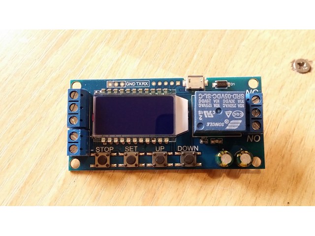
P04 Product Highlights: 1. Display with LCD two columns, Can display parameters directly; 2. Trigger mode: high and low level,switch quantity.meet most of the needs. 3. Power supply: 6~30V, also supports micro USB 5.0V, very convenient.Anti back connection of power supply. 4. Parameters can be modified via UART. 5. Stop button to provide emergency stop function. 6. 5 minutes without any operation into a low-power state. Any action wake up. 7. OP/CL/LOP params can be modified individually 8. All parameters are automatically saved by power off. Working Mode Introduction(P1~P7) P1: After the signal is triggered, the relay conduction in OP time then disconnects; In the OP time, the signal is invalid. P2: After the signal is triggered, the relay conduction in OP time then disconnects; In the OP time, the signal triggers a new timer. P3: After the signal is triggered, the relay conduction in OP time then disconnects; In the OP time, signal trigger reset timer,relay disconnected and stop timing. P4: When triggered, After the relay is disconnected from CL time, relay conduction OP time, after timing is complete, disconnect relay. P5: When triggered, After the relay conduction op time, the relay disconnects the CL time, and then loops the above action, gives the signal again in the loop, relays disconnect, stops the timer, and the number of cycles (LOP) can be set; P6: When triggered, After the relay conduction op time, the relay disconnects the CL time, and then loops the above action, signal is invalid in the loop, the number of cycles (LOP) can be set; P7: Signal hold function: The signal is maintained, the timing is cleared, and the relay conduction; when the signal disappears, the relay disconnects after the timing OP; during the timing, there is another signal and the timing is cleared; Product Parameters: 1. Power Supply: 6V~30V and micro USB 5.0 V 2. Trigger signal source: High level(3.0V~24.0V),Low level(0.0V ~0.2V),Switch signal. 3. Maxmum Output load: DC 30V 5A and AC 220V 5A. 4. Static Current: 15mA Operating current: 50mA. 5. Service life: more than 100,000 times; working temperature: -40-85°C; size: 8.0*3.8*1.9cm. 6. Optocoupler isolation,Strong anti-interference ability, Industrial grade circuit board Timing Range: 0.01 sec~9999 min How to choose the timing range: In the OP/CL parameter modification interface, press the STOP button shortly to select the timing range. XXXX Timing range:1sec~9999sec XXX.X Timing range:0.1sec~999.9sec XX.XX Timing range:0.01sec~99.99sec X.X.X.X Timing range:1min~999.9min For example, if you want to set the OP to 3.2 seconds, move the decimal point to ten digits. LCD display 003.2 Parameter Description: OP on-time, CL off time, LOP cycle times (1 - 9999 times, `----` represents an infinite number of cycles) Parameter Settings: a) Press and hold the SET key to enter the setting interface; b) First set the working mode, work mode flashes reminder, set the working mode by pressing the UP / DOWN keys; c) Short press the SET button to select the working mode and enter the system parameter settings. d) In the system parameter setting interface, press SET key to switch the system parameters to be modified, and press / long press UP/DOWN key to modify. (Note: Short press SET in P-1~P-3, P-7 mode is invalid); e) In the OP/CL parameter modification interface, short press STOP to switch the timer unit (1s/0.1s/0.01s/1min); f) After all parameters are set, press and hold the SET button for more than 2 seconds to release the hand, save the parameter settings and exit the setting interface
Istorija cene
Naziv oglasa
Početna cena
Najveća cena
Najniža cena
Nema podataka o istoriji cene

Pretraga: " "
Uspešno ste zapratili pretragu.
Sve zapraćene pretrage možete videti u
korisničkom panelu.