

Pratite promene cene putem maila
- Da bi dobijali obaveštenja o promeni cene potrebno je da kliknete Prati oglas dugme koje se nalazi na dnu svakog oglasa i unesete Vašu mail adresu.
1-25 od 30 rezultata
1-25 od 30 rezultata
Prati pretragu "b"
Vi se opustite, Gogi će Vas obavestiti kad pronađe nove oglase za tražene ključne reči.
Gogi će vas obavestiti kada pronađe nove oglase.
Režim promene aktivan!
Upravo ste u režimu promene sačuvane pretrage za frazu .
Možete da promenite frazu ili filtere i sačuvate trenutno stanje
-
Mašine i alati chevron_right Ručni alat i rezervni delovi
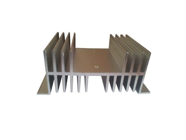
- Univerzalni hladnjak za SSR, - SSR Struja (na 25°C): 40A, - SSR Faze: Monufazni, - Dimenzije (V x Š x D): 35mm x 150mm x 90mm.
-
Mašine i alati chevron_right Ručni alat i rezervni delovi
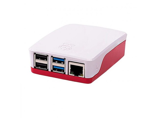
- Kućište za RaspberryPi 4 B, - Otvori za dual micro HDMI, Audio/Video, USB i Ethernet portove, kao i USB-C napojni konektor i otvor za microSD karticu, - Poklopac se može skinuti ukoliko se koristi HAT, - Materijal: ABS, - Boja: belo-crvena, - Dimenzije: 97 x 70 x 25mm.
-
Mašine i alati chevron_right Ručni alat i rezervni delovi
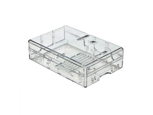
- Kućište za RaspberryPi 3 B i RaspberryPi 3 B+, - Materijal: Polikarbonat, - Boja: transparentno, - Dimenzije: 25.4 x 63.5 x 88.9mm.
-
Mašine i alati chevron_right Ručni alat i rezervni delovi
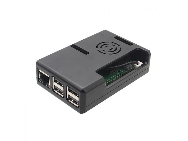
- Kućište za RaspberryPi 3 B i RaspberryPi 3 B+, - Rupa za ventilator, - Materijal: ABS, - Boja: crna, - Dimenzije: 90 x 62 x 26mm, - Težina: 37g.
-
Mašine i alati chevron_right Ručni alat i rezervni delovi
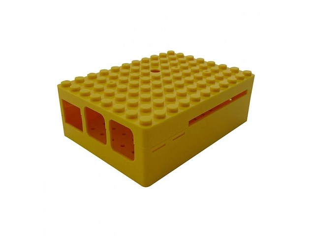
- Kućište za RaspberryPi 3 B ili RaspberryPi 3 B+, - Materijal: ABS, - Boja: žuta, - Otvori za I/O portove se nalaze na bočnoj strani kućišta, - Dimenzije: 88.8 x 64.5 x 30.5mm.
-
Mašine i alati chevron_right Ručni alat i rezervni delovi
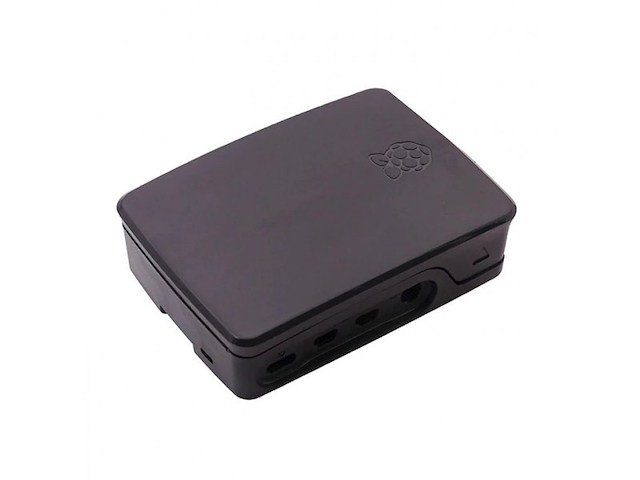
- Kućište za RaspberryPi 4 B, - Materijal: ABS, - Na kućištu su otvori za: dual micro HDMI, audio/video, USB, Ethernet portove, USB C konektor za napajanje i pristup microSD kartici, - Boja: crna, - Karakteristike: jednostavno za sklapanje, otporan na prašinu, izdržljiv.
-
Mašine i alati chevron_right Ručni alat i rezervni delovi
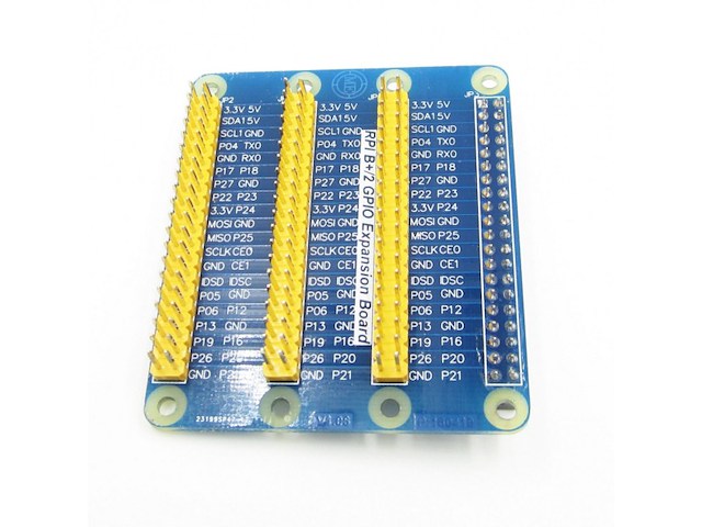
Ova GPIO ploča je namenjena za povezivanje senzora, relea, uredjaja i drugih elektronskih komponenti na GPIO port od Raspberry Pi-a. Ima integrisan konektor, tako da se samo nabode na iglice Raspberry Pi-a. Ima svoje izvode za 3.3V i 5V koje vuče sa Raspberry Pi-a. Šifra: D1011

-
Mašine i alati chevron_right Ručni alat i rezervni delovi
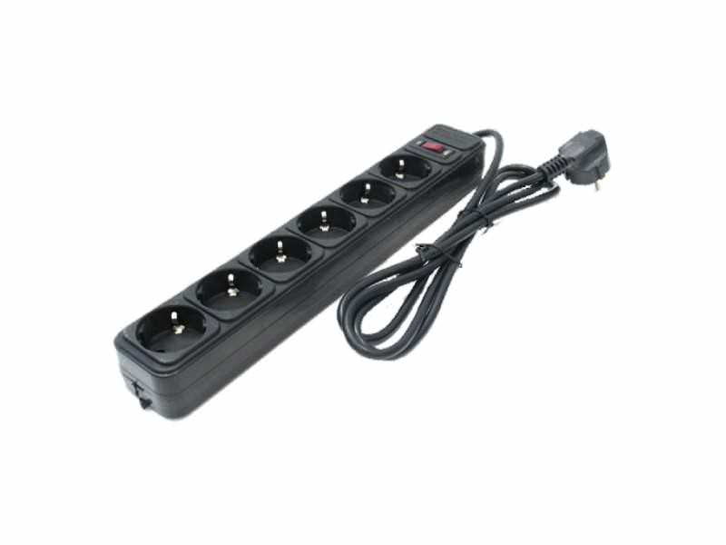
Max. opterećenje : 250 V~ / 16 A / 3500 W Kabel : H05VV-F 3x1.5 mm2 Broj utičnica : 6 Prekidač : Da Boja : Crna Dužina kabela : 3 m IP zaštita : IP20 Zaštita za decu : Ne Zaštita do : 4500 V / 4500 A ---------------- Razvodnik sa 6 utičnica, sa prenaponskom zaštitom Za priključenje više uređaja u jednu mrežnu utičnicu Pogodan za zaštitu kućnih aparata
-
Mašine i alati chevron_right Ručni alat i rezervni delovi
Max. opterećenje : 250 V~ / 16 A / 3500 W Kabel : H05VV-F 3x1.0 mm2 Broj utičnica : 6 Prekidač : Da Boja : Crna Dužina kabela : 4.5 m IP zaštita : IP20 Zaštita za decu : Ne Zaštita do : 4500 V / 4500 A ---------------- Razvodnik sa 6 utičnica, sa prenaponskom zaštitom Za priključenje više uređaja u jednu mrežnu utičnicu Pogodan za zaštitu kućnih aparata
-
Mašine i alati chevron_right Ručni alat i rezervni delovi
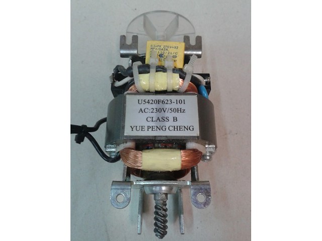
elektromotor 230v,50hz,class B,tip U5420F623-101,polovan,koriscen,ispravan,neznam za koji uredjaj se koristi.za sve informacije pitajte.
-
Mašine i alati chevron_right Ručni alat i rezervni delovi
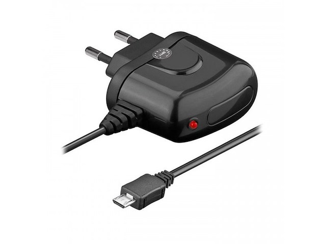
- Ulazni napon: 100 - 240VAC, - Izlazni napon: 5VDC, - Max jačina izlazne struje: 1200mA, - Priključak USB 2.0 Type B micro, - Dužina kabla: 1.4m.
-
Mašine i alati chevron_right Ručni alat i rezervni delovi
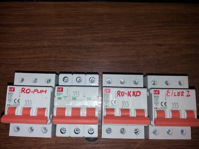
-LS BKN C63 -LS BKN-b C32 -LS BKN C25 -LS BKN C40 -Cena je po komadu. -Za kupovinu svih tropolnih automatskih osiguraca cena je samo 3000 dinara!
-
Mašine i alati chevron_right Ručni alat i rezervni delovi
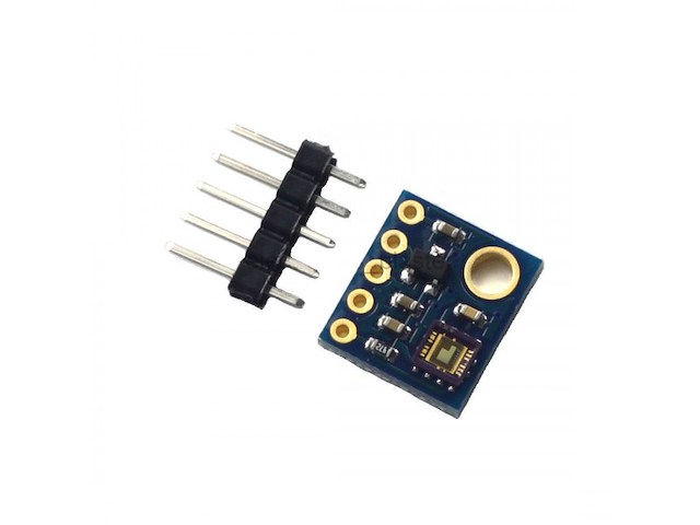
Ovaj senzor je namenjen za merenje UV-A i UV-B zračenja. Uz pomoć fotodetektora, pretvara jačinu struje u napon, koji se dalje šalje kao analogni signal. Šifra: B1082
-
Mašine i alati chevron_right Ručni alat i rezervni delovi
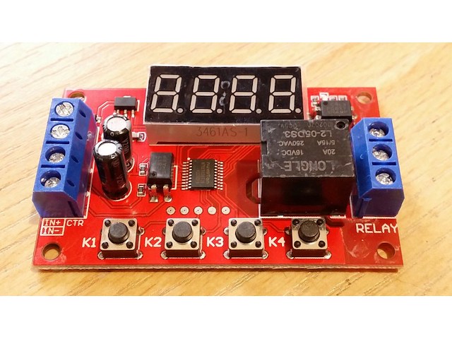
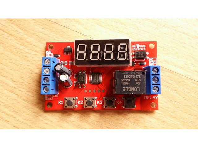
P04 The multi-function relay control module is specially designed for users with many different needs. It adopts a microcontroller as the main control unit and presets 32 kinds of functions, and users can use corresponding specific functions according to actual needs. It can be applied to water pump control, motor control, lamp strip control, solenoid valve control, etc. 1. New upgrade, the module function is increased to 32 kinds, to meet more application needs. 2. The power supply anti-reverse function will not damage the module due to wrong power supply. 3. Timing accuracy to 0.01 seconds timing. 0.1 seconds (minimum) ~ 999 minutes (maximum) optional 4. Low power consumption power saving setting, you can turn off the display area. Product parameters: Product Name: Multi-function time delay relay Relay V number: DC5V/12V/24V optional Input voltage: 5V version: DC5V power supply; 12V version: DC12V power supply; 24V version: DC24V power supply Output load: within 30V DC, maximum 10A. Within 250V, maximum 5A. Trigger signal: 5V version (high level: 5V); 12V version (high level: 12V), 24V version (high level: 24V) The low level is 0V. Quiescent current: 20mA Working current: 60mA Working temperature: -25℃-85℃ Power-off memory: Yes Product weight: ≈26g, product size: 65* 34.3 * 17.5 (MM L*W*H) The manual measurement is for reference only, the actual size is subject to the actual product Product Features: Wiring port description: DC+ Input DC power supply positive DC- Input DC power supply negative IN+ signal input positive IN- signal input negative NO relay normally open interface, the relay is short-circuited with COM when it is engaged, and it is suspended when not engaged; COM relay common terminal interface NC relay normally closed terminal interface, when the relay is not pulled in, it is short-circuited with COM, and it is left floating when pulled in; Instructions for use: Working mode (32 kinds): P-11: In jog mode, there is signal pull-in and no signal disconnect. P-12: Self-locking mode, the state of the relay reverses once after each trigger. P-13: After triggering, the relay will pull in and disconnect after delaying A time; the trigger will be invalid during the delay. P-14: After triggering, the relay will pull in, and it will be disconnected after the delay of A time; the trigger will be re-timed during the delay. P-15: After triggering, the relay will pull in, and it will be disconnected after the delay time A; during the delay time, the accumulated timer will be triggered. P-16: After triggering, the relay will pull in and disconnect after delaying time A; during the delay, a reset will be triggered (relay disconnected). P-17: After triggering, the relay pulls in for the duration of the signal, the input signal disappears, and then disconnects after the delay of A time; during the delay time, the relay is triggered again to keep the pull in, and the timing stops until the last signal disappears, delay A time Then disconnect. P-18: The relay will pull in immediately after power-on, and it will be disconnected after a delay of A second; until the next power-on. P-21: Give the signal, the relay will pull in after the delay of A time. P-22: Give a continuous signal, after the time exceeds A, the relay will pull in; when the signal disappears, the relay will open. P-23: When the signal disappears for more than A time, the relay pulls in; when there is a signal, the relay disconnects. P-24: Give a continuous signal. After the time exceeds A, the relay will pull in; when the signal disappears for more than time A, the relay will open. P-25: Give a continuous signal, the relay pulls in after exceeding A time; give a continuous signal again, the relay turns off after exceeding A time P-26: Give a signal, the relay will disconnect after A time pull-in; after the signal disappears, the relay will stop after A second pull-in. P-27: There is a pulse signal (rising edge or falling edge), the relay is disconnected, there is no pulse signal, the relay pulls in after the delay of A time (continuous high level or continuous low level are considered as no pulse). P-28: After power on, the relay will pull in after the delay time A until power off. The P-31: After power-on, the relay pulls in time A and turns off time B, in an infinite loop; power off stops. P-32: There is a continuous signal, the relay pulls in A time, disconnects B time, infinite loop; the signal disappears, and the loop is terminated. P-33: Give a signal once, the relay pulls in A time, disconnects B time, infinite loop; give another signal to terminate the loop. P-34: After power-on, the relay pulls in after the delay time A, and disconnects after pulling in the time B. P-35: Give a signal, after the delay time A, the relay pulls in and pulls off after the time B pulls in. P-36: Continuous signal is given. After the time A is exceeded, the relay is switched on and disconnected after the time B is switched on; the signal disappears, the timing is cleared, and the relay is turned off. P-37: There is a signal, the relay will be automatically disconnected after the A time is closed, and the B time will be counted after the disconnection. The signal trigger is invalid during the A+B time. P-38: There is a signal, the relay will be automatically disconnected after the time of pull-in A, after the time B is counted after the disconnection, it will be automatically disconnected after the time of pull-in A again. The P-41: The signal does not act; the signal disappears and triggers; the relay absorbs and merges after a delay of A time to disconnect. P-42: The signal disappears. After the delay time A, the relay pulls in; after the delay time B, the relay disconnects. P-43: The signal disappears. After the disappearance exceeds the time A, the relay pulls in; after delaying the time B, the relay opens. P-44: After power-on, the relay pulls in time A and turns off time B; after the cycle C times, the relay turns off and stops. P-45: No action after power on; after the signal is given, the relay pulls in the A time and disconnects the B time; the relay is turned off and stopped after C cycles; when the signal is given, it is executed again. P-46: After the signal is given more than A times, the relay pulls in; keeps pulling in; the power stops. P-47: After the signal exceeds A times, the relay pulls in; when it pulls in for B time, it is disconnected. P-48: During the C time, after continuously giving the signal more than A times, the relay will disconnect and stop after B time. Description table of the position of the decimal point and the time unit it represents: x.xx Decimal point is in the hundreds place, time range 0.01~9.99 seconds xx.x decimal point is in the tenth place, time range 0.1~99.9 seconds xxx has no decimal point, time range is 1~999 seconds xxx. The decimal point is in single digits, the time range is 1~999 minutes Turn off the display: In the non-setting state, press the K4 key to turn off the display, then press it again to turn on. Description of working parameter setting: Hold down the K1 key without letting go, after 2 seconds the display shows P-xx, press K2 and K3 to change the working mode. After selecting the working mode, short press K1 to enter the A time setting, the screen displays Axxx, then press K2 and K3 to modify the A time parameters, K2 and K3 key short press plus or minus 1, long press to quickly add and subtract 10, Press the K4 key to set the position of the decimal point. After setting the A time, press the K1 key to set the B time, the screen displays bxxx, then press the K2 and K3 keys to modify the B time parameters, K2 and K3 keys short press plus or minus 1, long press to quickly add and subtract 10, Press the K4 key to set the position of the decimal point. After setting the B time, (if the mode has the C cycle number parameter), then press the K1 key to set the C cycle number, the screen displays Cxxx, then press the K2 and K3 keys to modify the C cycle number parameter, K2 and K3 keys Short press to increase and decrease by 1, long press to increase and decrease by 10. After setting, press the K1 key once to exit the setting state and save all parameters.
-
Mašine i alati chevron_right Ručni alat i rezervni delovi
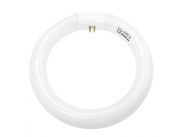
- Prstenasta fluo cev za lupu, - Zamena za oštećene ili pregorele cevi, - Upotrebljiva za većinu lampi sa lupom (preporučuje se za model NKL02, NKL03), - Napon napajnja: 230VAC, - Snaga: 22W, - Temperatura boje: 6400K, - Jačina svetlosti: 1050lm, - Klasa energetske efikasnosti: B, - Stepen IP zaštite: IP20, - Prečnik: 205mm (T8).
-
Mašine i alati chevron_right Ručni alat i rezervni delovi
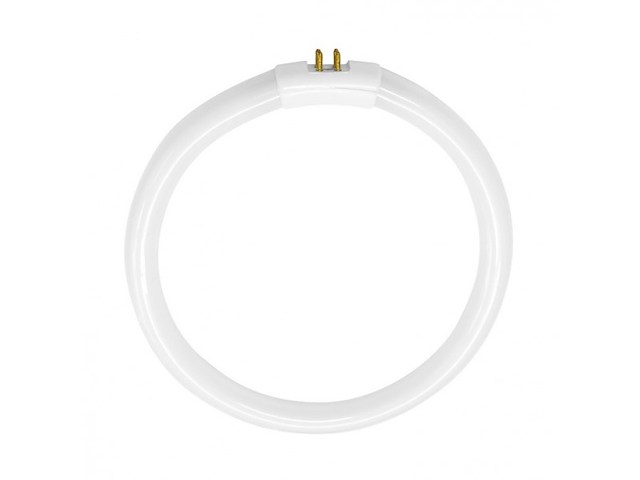
- Prstenasta fluo cev za lupu, - Zamena za oštećene ili pregorele cevi, - Upotrebljiva za većinu lampi sa lupom (preporučuje se za model NKL01), - Napon napajnja: 230VAC, - Snaga: 22W, - Temperatura boje: 6400K, - Jačina svetlosti: 1250lm, - Klasa energetske efikasnosti: B, - Stepen IP zaštite: IP20, - Prečnik: 184mm (T5).
-
Mašine i alati chevron_right Ručni alat i rezervni delovi
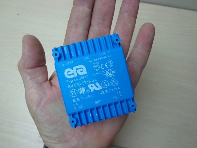
OPIS SKINUT SA NETA,,, UI 39-Flachtransformator 24 VA Primär: 2 x 115 V Sekundär: 2 x 12 V 2 x 1000 mA 24 VA - Neuteil - Daten für BV039/5239.0L Print-Flachtrans- formatoren Typ: UI 39/17 ( L x B x H ) 68 x 57 x 32 mm
-
Mašine i alati chevron_right Ručni alat i rezervni delovi
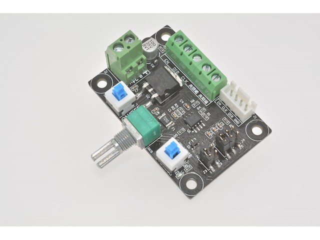
Feature: 1, this module is a pulse generation module, supply the control signal to stepper driver. To control the stepper motor, it must be equipped with a drive. 2, this simple controller + stepper motor + stepper motor + DC power supply can be composed of a simple set of control platform. 3, the controller has high 5.4k-160khz, middle 540-16.6khz, low 80-2.4khz total of 3 kinds of low frequency signal can be used to select the jumper. 4, can produce pulse signal, can also produce PWM signal, can choose the jumper. 5, the frequency of measurement: PUL and common cathode end. Different stepper driver may mark different name EN=ENA=FREE Enable PUL=PULS=CLK Pulse DIR=CW=CWW Direction Common anode Connection method (B) EN+ PUL+ DIR+ connect together to com+。 EN- connect EN PUL- connect CLK DIR- connect DIR Common cathode Connection method (B) EN- PUL- DIR- connect together to com-。 EN+ connect EN PUL+ connect CLK DIR+ connect DIR
-
Mašine i alati chevron_right Ručni alat i rezervni delovi
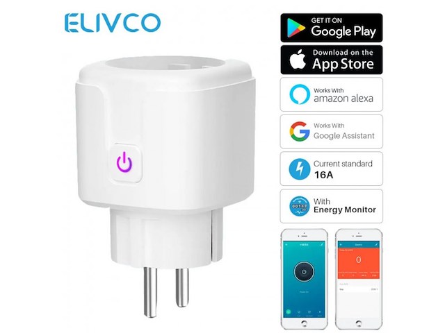
Smart utičnica se jednostavno povezuje na bežični ruter Omogućava daljinsku kontrolu priključenih uređaja preko mobilnog telefona Uređaji se takođe mogu uključivati prema vremenskom rasporedu Kompatibilna sa Google Home i Amazon Alexa Odgovarajuća aplikacija je eWeLink Praćenje potrošnje preko aplikacije Wi-Fi protokol 2.4 GHz, 802.11 b/g/n Maksimalno opterećenje: 16 A / 3500 W Napajanje: 230 V~ / 50 Hz
-
Mašine i alati chevron_right Ručni alat i rezervni delovi
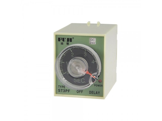
Vremenski relej sa zakašnjenjem pri uključivanju! Nakon dobijanja upravljačkog napona kasni sa pomerajem svojih kontakata za unapred zadano vreme. - Artikal: rele vremenski (FULI), - Model / Tip: ST3P A-B, - Nazivni Napon: 200-220 V AC, - Nazivna Struja: 3 A, - Vremenski Interval: 1s/10s/60s/6min., - Broj Pinova: 8, - Način / Tip Montaže: na podnozje PF083, - Temperatura Okruženja (ºC): -40°C do + 60°C, - IP Zaštita: IP 20.
-
Mašine i alati chevron_right Ručni alat i rezervni delovi
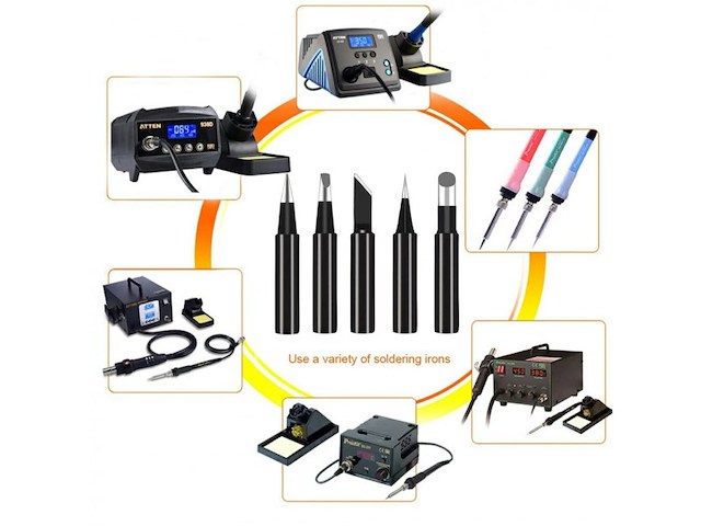
133. *Set od 5kom. vrhova za lemilicu odgovara za: 936.937,938.900M,933.907,951.898D,852D+,952D,913 itd. Modeli vrhova: I, B, D2,4,3C, KE50. Temperaturni opseg: 200° C-480° C **Robu šaljem kao preporuceno pismo u vazdusnoj koverti sa pracenjem, cime je postarina samo 200din. (na Vašu odgovornost) nakon uplate na moj racun ili Postexpressom kurirskom sluzbom (pouzecem) robu placate prilikom preuzimanja. Naravno moze i licno preuzimanje kome vise odgovara.
-
Mašine i alati chevron_right Ručni alat i rezervni delovi
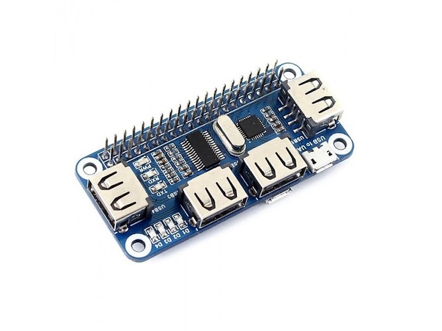
- Raspberry Pi USB ekspanzija sa 4 porta, - Kompatibilan za sledeće Raspberry Pi modele: 3, 2, B+, Zero, Zero W, - Radni napon: 5V, - Poseduje 4 USB porta kompatibilna sa USB 2.0 i 1.1 brzinom prenosa, - USB na UART za serijsko otklanjanje grešaka, - Višestruki indikatori za lak pristup napajanju, USB na UART i USB interfejs za proširenje, - Prečnik otvora za montažu: 3mm, - Dimenzije pločice: 65 x 30mm.
-
Mašine i alati chevron_right Ručni alat i rezervni delovi
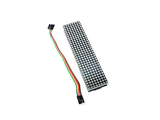
Dot Led matriks modul 8x8 sa MAX7219 cetvorostruki. Modul dolazi kompletno sklopljen i sa kablicima. Product Description The MAX7219 are compact, serial input/output common-cathode display drivers that interface microprocessors (μPs) to 7-segment numeric LED displays of up to 8 digits, bar-graph displays, or 64 individual LEDs. Included on-chip are a BCD code-B decoder, multiplex scan circuitry, segment and digit drivers, and an 8x8 static RAM that stores each digit.Only one external resistor is required to set the segment current for all LEDs. The MAX7219 is compatible with SPI™, QSPI™, and Microwire™, and has slew-ratelimited segment drivers to reduce EMI.A convenient 3-wire serial interface connects to all common μPs. Individual digits may be addressed and updated without rewriting the entire display. The MAX7219 also allow the user to select code-B decoding or no-decode for each digit.The devices include a 150μA low-power shutdown mode, analog and digital brightness control, a scanlimitregister that allows the user to display from 1 to 8 digits, and a test mode that forces all LEDs on. Features: A single module can drive a 8x8 dot matrix common cathode Module Working voltage: 5V Module size: 12.8 cm X3.2 cm X1.3 cm(L*W*H) With 64 fixing screw holes, Hole diameter 3mm Module with input and output interfaces, support for cascading multiple modules Wiring:for example 51 SCM VCC→5V GND→GND DIN→P2.2 CS →P2.1 CLK→P2.0
-
Mašine i alati chevron_right Ručni alat i rezervni delovi
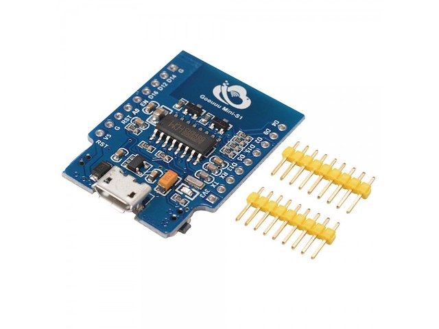
Ovaj modul je namenjen za projekte gde se trebaju povezati serijski protokol sa WiFi mogućnostima, uz podršku jedno 32 bitnog MCU-a. Podržava Wifi b g i n protokole. Tehničke karakteristike: Built-in Tensilica L106 ultra low power 32-bit micrMCU, with 16-bit streamlined mode, clocked at 80 MHz and 160MHz, support RTOS WIFI @ 2.4 GHz, support WPA / WPA2 security mode Built-in 10 bit high precision ADC Built-in TCP / IP protocol stack Built-in TR switch, balun, LNA, power amplifier and matching network Built-in PLL, regulator and power management components 802.11b mode + 20 dBm output power Supports antenna diversity The deep sleep hold current is 20uA and the shutdown current is less than 5uA can be doubled as application processor SDI2.0, SPI, UART STBC, 1x1 MIMO, 2x1 MIMA-MPDU, A-MSDU aggregation and 0.4 s protection interval Within 2ms wake up, connect and pass the packet standby power consumption less than 1.0mW (DTIM3) support AT remote upgrade and cloud OTA upgrade Supports STA / AP / STA + AP operation mode Šifra: B1120
Istorija cene
Naziv oglasa
Početna cena
Najveća cena
Najniža cena
Nema podataka o istoriji cene

Pretraga: " "
Uspešno ste zapratili pretragu.
Sve zapraćene pretrage možete videti u
korisničkom panelu.